EasyManua.ls Logo

Sunx FX-101 User Manual

Sunx FX-101
5 pages
To Next Page IconTo Next Page
Page #1 background imageLoading...
Page #1 background image
Thank you very much for using SUNX products. Please read this Instruc-
tion Manual carefully and thoroughly for the correct and optimum use of this
product. Kindly keep this manual in a convenient place for quick reference.
FX-100 Series
INSTRUCTION MANUAL
Digital Fiber Sensor
Photoelectric Sensor
MJE-FX100 No.0007-43V
WARNING
Never use this product as a sensing device for personnel protection.
In case of using sensing devices for personnel protection, use products
which meet laws and standards, such as OSHA, ANSI or IEC etc., for
personnel protection applicable in each region or country.
Ɣ
Ɣ
+RZWRFRQQHFWWKH¿EHUFDEOH
%HVXUHWR¿WWKHDWWDFKPHQWWRWKH¿EHUV¿UVWEHIRUHLQVHUWLQJWKH¿EHUVWRWKH
DPSOL¿HU)RUGHWDLOVUHIHUWRWKH,QVWUXFWLRQ0DQXDOHQFORVHGZLWKWKH¿EHUV
1. Snap the fiber lock lever down, till it stops
completely.
2. Insert the fiber cables slowly into the inlets
until they stop. (Note 1)
5HWXUQWKH¿EHUORFNOHYHUWRWKHRULJLQDOSRVL-
tion, till it stops.
1
3
2
Fiber lock
lever
Fiber
MOUNTING
2
+RZWRPRXQWWKHDPSOL¿HU
)LWWKHUHDUSDUWRIWKHPRXQWLQJVHFWLRQRIWKH
DPSOL¿HURQDPPZLGWK',1UDLO
2. Press down the rear part of the mounting
VHFWLRQRIWKHXQLWRQWKHPPZLGWK',1UDLO
DQG¿WWKHIURQWSDUWRIWKHPRXQWLQJVHFWLRQ
WRWKH',1UDLO
1
2
35mm width DIN rail
:KHQXVLQJD',1UDLO!
+RZWRUHPRYHWKHDPSOL¿HU
3XVKWKHDPSOL¿HUIRUZDUG
/LIWXSWKHIURQWSDUWRIWKHDPSOL¿HUWRUHPRYH
it.
1
2
:KHQXVLQJVFUHZVZLWKZDVKHUV!
Use M3 screws with washers for mounting.
7KHWLJKWHQLQJWRUTXH VKRXOGEH 1ÂPRU
less.
Ɣ
M3 screw
with washer
1RWH 7DNHFDUHWKDWLIWKHIURQWSDUWLVOLIWHGZLWKRXWSXVKLQJWKHDPSOL¿HUIRUZDUGWKH
hook on the rear portion of the mounting section is likely to break.
1RWHV,QFDVHWKH¿EHUFDEOHVDUHQRWLQVHUWHGWRDSRVLWLRQZKHUHWKH\VWRSWKH
VHQVLQJUDQJHUHGXFHV6LQFHDÀH[LEOH¿EHULVHDVLO\EHQWWDNHFDUHZKHQ
it is inserted.
:LWKWKHFRD[LDOUHÀHFWLYHW\SH¿EHUVXFKDV)'* or )')0, insert the
VLQJOHFRUH¿EHUFDEOHLQWRWKHEHDPHPLWWLQJ LQOHW ³3´DQGWKHPXOWLFRUH
¿EHUFDEOHLQWRWKHEHDPUHFHLYLQJLQOHW³'´,IWKH\DUHLQVHUWHGLQUHYHUVH
the sensing performance will deteriorate.
3$57'(6&5,37,21
1
MODE key
ON key /
Set value UP key
Operation indicator
(Orange)
OFF key /
Set value DOWN key
Digital display (Green)
(Threshold value)
Digital display (Red)
(Incident light intensity)
2SHUDWLQJSRUWLRQ!
02'(NH\
ON key /
Set value UP key
2))NH\
6HWYDOXH'2:1NH\
Â6HOHFWLRQRIVHWWLQJLWHPV
Â&RQ¿UPDWLRQRIVHWFRQWHQWV
Â6HOHFWLRQRIVHWWLQJFRQWHQWV
Â6HWWLQJVLQWHDFKLQJPRGH
1RWH &DQFHOODWLRQ LV SRVVLEOHZKHQSUHVVLQJ02'(NH\IRU VHFRUPRUHLQSUR-
FHVVRIVHWWLQJVH[FHSWIRU581PRGHWKHQUHWXUQVWR581PRGH
Release
lever
Note: Take care that if the connector is pulled out without
pressing the release lever, cable or connector may
break.
'LVFRQQHFWLRQPHWKRG
Pressing the release lever of the cable with con-
nector, pull out the connector.
Ɣ
&RQQHFWRUSLQDUUDQJHPHQW!
Connector pin No. Terminal name
1+V
2 Output
3 ([WHUQDOLQSXW
40V
1
2
3
4
Insert the cable with connector &1$&Ƒinto
this product's connector area as shown in the
right figure.
Ɣ
WIRING
3
&RQQHFWLRQPHWKRG
Cable with
connector
CN-14A-CƑ
58102'(
5
7KUHVKROGYDOXH¿QHDGMXVWPHQWIXQFWLRQ
)LQHDGMXVWPHQWRIWKUHVKROGYDOXHFDQEHGRQHZKHQLQ581PRGH
3UHVVWKHVHWYDOXH83NH\RUVHWYDOXH'2:1NH\WRFKDQJHWKUHVKROG
value. (Hold down the key to make the value change faster.)
The threshold value is stored after 3 sec.
Ɣ
Ɣ
Ɣ
<When in RUN mode>
Incident light
intensity
Threshold
value
<When turning ON the power>
Emission
frequency
Product
name
<RUN mode>
Incident light
intensity
Threshold
value
Automatic
When turning ON the power, the product name is indicated on the green
digital display, while the emission frequency is indicated on the red digital
display. Then switches into RUN mode [digital display (green: threshold
value, red: incident light intensity)].
Ɣ
'LJLWDOGLVSOD\!
:KHQVHOHFWLQJHPLVVLRQ KDOWLQ WKHH[WHUQDO LQSXWVHWWLQJPRGHDQGUH-
FHLYLQJWKHVLJQDOH[WHUQDOO\³
´LVLQGLFDWHGRQWKHUHGGLJLWDOGLVSOD\
:KHQVHOHFWLQJ(&2LQWKHH[WHUQDOLQSXWVHWWLQJPRGHNH\RSHUDWLRQRQ
WKHPDLQERG\LVLQYDOLGGXULQJH[WHUQDOLQSXW
:KHQVHOHFWLQJSRLQWWHDFKLQJLQWKHH[WHUQDOLQSXWVHWWLQJPRGH³ ´
is indicated on the green digital display after inputting the first point.
:KHQ(&2VHWWLQJPRGHLV21WKHGLJLWDOGLVSOD\WXUQVRIILQDSSUR[
sec. In case of lighting up the digital display again, press any key for 2
sec. or more.
)RUWKHVHWWLQJVRIH[WHUQDOLQSXWDQG(&2UHIHUWR³
35202'(´
Ɣ
Ɣ
Ɣ
Ɣ
Ɣ
,2&,5&8,7',$*5$06
131RXWSXWW\SH!
+
8V
*1
Main circuit
Internal circuit Users’ circuit
100mA max.
(Brown) +V
(Black) Output
(Blue) 0V
(White) External input
Color code of cable with connector
12 to 24V DC
±10%
Load
Connector pin No.
313RXWSXWW\SH!
*2
Main circuit
Internal circuit Users’ circuit
100mA max.
(Brown) +V
(Black) Output
(Blue) 0V
(White) External input
Color code of cable with connector
+
12 to 24V DC
±10%
Load
Connector pin No.
*1
Non-voltage contact or NPN open-collector transistor
or
+LJK9WR9'&RU2SHQ,QYDOLG
/RZ>WR9'&6RXUFHFXUUHQWP$RUOHVV@9DOLG
*2
Non-voltage contact or PNP open-collector transistor
or
+LJK>9WR9'&6LQNFXUUHQWWRP$RUOHVV@9DOLG
/RZWR9'&RU2SHQ,QYDOLG
'LJLWDO¿EHUVHQVRU);VHULHVKDVEHHQPRGL¿HGVLQFH
SURGXFWLRQLQ 'HFHPEHU+HQFHWKLVLQVWUXFWLRQ
PDQXDOKDVEHHQFKDQJHGWRUHÀHFWWKHPRGL¿FDWLRQV
Phone: 800.894.0412 - Fax: 888.723.4773 - Web: www.clrwtr.com - Email: info@clrwtr.com
Question and Answer IconNeed help?

Do you have a question about the Sunx FX-101 and is the answer not in the manual?

Sunx FX-101 Specifications

General IconGeneral
BrandSunx
ModelFX-101
CategoryAccessories
LanguageEnglish

Summary

Part Description

Operating Portion

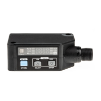
Details the function of operational keys and displays for sensor settings and modes.

Digital Displays

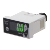
Information on the green and red digital displays indicating threshold values and incident light intensity.

Mounting

DIN Rail Mounting

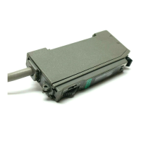
Instructions for mounting the amplifier unit onto a 35mm width DIN rail and removing it.

Screw Mounting

Guidance on using M3 screws with washers for mounting, including tightening torque.

Fiber Cable Connection

Steps for correctly connecting fiber cables to the sensor amplifier unit.

Wiring and Circuit Diagrams

Connection Method

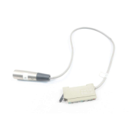
Details on connecting the sensor using a cable with a CN-14A-C connector.

Disconnection Method

Instructions for safely disconnecting the cable connector by pressing the release lever.

Connector Pin Arrangement

Diagram showing the pin numbers and their corresponding terminal names (+V, Output, External input, OV).

NPN Output Circuit Diagram

Schematic illustrating the I/O circuit for NPN output type sensors.

PNP Output Circuit Diagram

Schematic illustrating the I/O circuit for PNP output type sensors.

Run Mode Operation

Digital Display in Run Mode

Describes the initial display upon power-on and the normal display during RUN mode.

Threshold Value Fine Adjustment

Explains how to adjust the threshold value using the UP/DOWN keys while in RUN mode.

Setting Mode

Keylock Function

Details on how the keylock function prevents inadvertent changes to settings.

Setting Mode Navigation

Explains how to enter and exit setting mode using the MODE key.

Output Operation Setting

Configuration options for output operation, including Light-ON or Dark-ON.

Timer Operation and Delays

Settings for timer operations, including ON delay, OFF delay, and selectable delay times.

Emission Amount and Frequency

Adjustments for emission amount levels and emission frequency for optimal performance.

Teaching Mode

2-Point Teaching

Method for setting threshold values by teaching object present and absent conditions.

Limit Teaching

Method for setting threshold values by teaching only the object absent condition.

Full-Auto Teaching

Process for setting threshold values without stopping the assembly line for moving objects.

PRO Mode

PRO Mode Navigation

Instructions on how to enter PRO mode for advanced settings.

Shift Setting Mode

Adjusting the shift amount for limit teaching, from 0 to 80%.

External Input Setting Mode

Configuring external inputs for functions like emission halt, limit teaching, and ECO.

Threshold Value Storing

Setting modes related to storing threshold values based on external input selections.

Threshold Value Follow-up Cycle

Setting the cycle for the threshold value to follow incident light intensity variations.

GETA Function Setting

Adjusting incident light intensity to a target value for compensation.

ECO Setting Mode

Enabling ECO mode to turn off the digital display after a period of inactivity.

Inverting Digital Display

Option to invert the digital display for better visibility.

Threshold Value Margin Setting

Checking and setting the margin for the threshold value against incident light intensity.

Setting Copy Mode

Function to copy settings from a master side amplifier to a slave side amplifier.

Reset Mode

Returning the sensor's settings to their default factory configurations.

External Input Settings

External Input Functionality

Details on how external inputs affect sensor operation like emission halt and teaching.

Alert Output of External Input

Configuration for alert outputs based on external input conditions and threshold margins.

Setting Copy Function

Copying Master to Slave Settings

Procedure for copying settings from a master amplifier to a slave amplifier.

Canceling Copy Operation

How to cancel the setting copy operation by pressing the MODE key.

Quick Setting Function

Using Quick Setting

Description of selecting and setting parameters using quick setting mode.

Table of Quick Setting Numbers

Reference table for quick setting codes related to various sensor functions.

Code Setting Function

Setting Parameters via Codes

Method for setting output operation, timer, and other parameters using code combinations.

Code Table Reference

Detailed table mapping code digits to specific sensor settings like output and timer.

Specifications

Model and Sensing Range

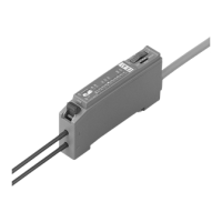
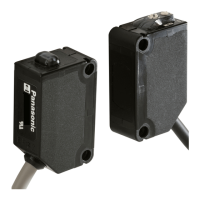
Overview of available models (FX-101, FX-102) and their sensing range options.

Output Characteristics

Details on NPN and PNP output types, including sink/source current and residual voltage.

External Input Specifications

Input impedance and signal conditions for NPN and PNP external inputs.

Response Time

Information on response times based on emission frequency settings.

Environmental and Material Specs

Operating/storage temperatures, humidity, emitting element, material, and accessory details.

Error Indication

Error Codes and Measures

Table listing error codes (EEPROM, short-circuit, communication) and recommended actions.

Modified vs. Conventional Units

Identifying Modified Units

Distinguishes modified units by a 'P' mark near the beam emitting inlet.

Cautions

General Safety Precautions

Important warnings regarding power supply, voltage, wiring, and noise interference.

Usage Environment

Guidelines on avoiding direct sunlight, dust, oil, and inflammable gases for proper operation.

Product Modification and Lifetime

Advisories against disassembling the product and limitations on EEPROM write cycles.

Related product manuals