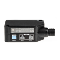
SENSITIVITY SETTING
7
٨
٨
٨
When the mode selection switch is set to 'SET' or 'MODE', the sensor is
more susceptible to extraneous light. Hence, when sensing objects, ensure to set
the mode selection switch to 'RUN'.
When the mode selection switch is changed from 'SET' to 'RUN' or from 'MODE'
to 'RUN', the set sensitivity or the contents of each mode setting are stored in an
EEPROM. Since the EEPROM has a life time, the sensitivity setting cannot be
done for more than 100,000 times.
Do not move or bend the fiber cable after the sensitivity setting. Detection may
become unstable.
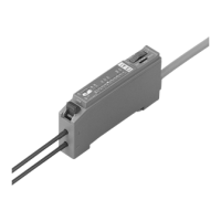
PART DESCRIPTION
5
Operation indicator (Orange)
Level indicators (Green)
Jog switch
Mode selection switch
Stability indicator (Green)
JOG SWITCH & LEVEL INDICATOR FUNCTION
6
Function
Press
3 sec. or more
Tu rn
Jog switch Operation
In 2-level teaching, it sets the sensitivity.
In limit teaching, it stores the incident light intensity in the object absent condition.
Each item is selected and the item or the contents of each item to be set is decided.
In limit teaching, it determines the direction of shift of the sensitivity.
It does fine adjustment of the set sensitivity.
The contents of each item are selected.
In full auto-teaching, it sets the sensitivity.
㧗
㧙
٨ Functions of jog switch
٨
Functions of level indicators
If the mode selection switch is set to 'SET' or 'RUN', the level indicators show the
position of the set sensitivity level. However, if the mode selection switch is set to
'MODE', the level indicators show the output operation/emission frequency/timer
settings.
*: The sensitivity level is changed in the range 0 to 999 within the sensor.
Hundreds position: lights up continuously
Tens position: blinks
Units position: not shown
Sensitivity level is displayed.
Hundreds position: lights up continuously
Tens position: not shown
Units position: not shown
Sensitivity level is displayed.
Item being set: blinks
Remaining 2 items: light up
continuously
Each mode is displayed.
Mode selection switch
Function
SET MODE
RUN
SET MODE
RUN
SET MODE
RUN
L-ON
D-ON
FR1
FR2
FR3
NON
OFD
9
8
7
6
5
4
3
2
1
0
Hundreds position
Set sensitivity
Tens position
L-ON
D-ON
FR1
FR2
FR3
NON
OFD
9
8
7
6
5
4
3
2
1
0
Output
operation
Timer
operation
Each mode
Emission
frequency
Hundreds position
Set sensitivity
L-ON
D-ON
FR1
FR2
FR3
NON
OFD
9
8
7
6
5
4
3
2
1
0
CAUTIONS
2
٨
٨
٨
٨
٨
٨
٨
٨
٨
٨
٨
٨
٨
Make sure to carry out the wiring in the power supply off condition.
Verify that the supply voltage variation is within the rating.
In case noise generating equipment (switching regulator, inverter motor, etc.) is used in the vicinity
of this product, connect the frame ground (F.G.) terminal of the equipment to an actual ground.
If power is supplied from a commercial switching regulator, ensure that the frame
ground (F.G.) terminal of the power supply is connected to an actual ground.
Do not use during the initial transient time (0.5 sec.) after the power supply is switched on.
The self-diagnosis output is not incorporated with a short-circuit protection. Do not
connect it directly to a power supply or a capacitive load.
Do not run the wires together with high-voltage lines or power lines or put them in
the same raceway. This can cause malfunction due to induction.
Extension up to total 100m is possible with a 0.3mm
2
, or more, cable. However, in
order to reduce noise, make the wiring as short as possible.
This sensor is suitable for indoor use only.
Avoid dust, dirt, and steam.
Take care that the product does not come in direct contact with organic solvents, such as, thinner, etc.
This sensor cannot be used in an environment containing inflammable or explosive gases.
Never disassemble or modify the sensor.
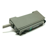
MOUNTING
3
Ԙ
ԙ
Fit the rear part of the mounting section of the amplifier
on the attached amplifier mounting bracket (MS-DIN-2)
or a 35mm width DIN rail.
Press down the rear part of the mounting section of the
unit on the attached amplifier mounting bracket
(MS-DIN-2) or a 35mm width DIN rail and fit the front
part of the mounting section to the attached amplifier
mounting bracket (MS-DIN-2) or a 35mm width DIN rail.
Attached amplifier mounting
bracket or 35mm width DIN rail
Ԙ
ԙ
How to mount the amplifier
How to remove the amplifier
Ԙ
ԙ
Push the amplifier forward.
Lift up the front part of the amplifier to remove it.
Ԙ
ԙ
Take care that if the front part is lifted without pushing the
amplifier forward, the hook on the rear portion of the mounting
section is likely to break.
Note:
I/O CIRCUIT DIAGRAMS
4
٨ NPN output type
D
1
100mA max.
50mA max.
(Brown) +V
(Black)
Sensing output
(Orange) Self-diagnosis output
12 to 24V DC
r10%
+
-
(Blue) 0V
Users' circuitInternal circuit
Color code
Sensor circuit
T
r1
Z
D1
T
r2
Z
D2
Load
Load
Symbols... D1, D2
ZD1, ZD2, ZD3, ZD4: Surge absorption zener diode
Tr
1, Tr2
Tr 3, Tr4
: Reverse supply polarity protection diode
: NPN output transistor
: PNP output transistor
PNP output type٨
(Brown) +V
(Black)
Sensing output
(Orange)
Self-diagnosis output
(Blue) 0V
Users' circuitInternal circuit
Color code
D
2
50mA max.
100mA max.
12 to 24V DC
r10%
+
-
T
r4
Z
D4
T
r3
Z
D3
Sensor circuit
Load
Load
Note: Use the optional cable with a connector for the plug-in connector type.
Model No.: CN-54-C2 (cable length 2m), CN-54-C5 (cable length 5m)
Connector pin
position
+V
Sensing
output
0V
Self-
diagnosis
output
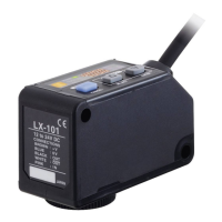
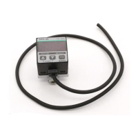
INSTRUCTION MANUAL
FX-A1 Series
Auto-setting Fiber Sensor
Thank you very much for using SUNX products. Please read this Instruction Manual
carefully and thoroughly for the correct and optimum use of this product. Kindly keep
this manual in a convenient place for quick reference.
٨
٨
Never use this product as a sensing device for personnel protection.
In case of using sensing devices for personnel protection, use
products which meet standards, such as OSHA, ANSI or IEC etc.,
for personnel protection applicable in each region or country.
WARNING
SPECIFICATIONS
1
NPN open-collector transistor
Maximum sink current: 50mA
Applied voltage: 30V DC or less
(between self-diagnosis output and 0V)
Residual voltage:
1V or less (at 50mA sink current)
0.4V or less (at 16mA sink current)
PNP open-collector transistor
Maximum source current: 50mA
Applied voltage: 30V DC or less
(between self-diagnosis output and +V)
Residual voltage:
1V or less (at 50mA source current)
0.4V or less (at 16mA source current)
NPN open-collector transistor
Maximum sink current: 100mA
Applied voltage: 30V DC or less
(between sensing output and 0V)
Residual voltage:
1V or less (at 100mA sink current)
0.4V or less (at 16mA sink current)
PNP open-collector transistor
Maximum source current: 100mA
Applied voltage: 30V DC or less
(between sensing output and +V)
Residual voltage:
1V or less (at 100mA source current)
0.4V or less (at 16mA source current)
Selectable, either Light-ON or Dark-ON, with jog switch
Incorporated
12 to 24V DCr10%˴Ripple P-P 10% or less
50mA or less
Output operation
Short-circuit protection
Sensing output
PNP output
Current consumption
Supply voltage
FX-A1P
Model No.
FX-A1
Item
Type
NPN output
Red LED type Red LED type
FX-A1G
Green LED type
Self-diagnosis output
Red LED (modulated)
Red LED (modulated)
Green LED (modulated)
ON in unstable sensing condition
0.2mm
2
4-core cabtyre cable, 2m long
Enclosure: Heat-resistant ABS, Enclosure cover: Polycarbonate
70g approx.
35 to 85% RH, Storage: 35 to 85% RH
-10 to +50 (No dew condensation or icing allowed), Storage: -20 to +70
Approx. 40ms fixed OFF-delay timer (switchable, either effective or ineffective)
Incorporated (up to three sets of fibers can be mounted adjacently)
MS-DIN-2 (Amplifier mounting bracket): 1 No.
Response
time
Ambient temperature
Timer function
Cable
Material
Weight
Ambient humidity
Emitting element
Sensitivity setting
Interference prevention function
Accessory
Output operation
Short-circuit protection
Emission frequency 1
0.65ms or less
Emission frequency 2
0.75ms or less
Emission frequency 3
0.5ms or less
2-level teaching / Limit teaching / Full auto-teaching
Note: For the plug-in connector type, add suffix 'J' at the end of the model No.
Model No.: FX-A1J, FX-A1GJ, FX-A1PJ
For the cable length 5m type, add suffix '-C5' at the end of the model No. (only NPN output type)
Model No.: FX-A1-C5, FX-A1G-C5
Ԙ
ԙ
Ԛ
Snap the fiber lock lever down.
Insert the fiber cables slowly into the inlets until
they stop. (Note 1)
Return the fiber lock lever to the original position,
till it stops.
Notes: 1)
2)
In case the fiber cables are not inserted to a position where they stop, the sensing range reduces.
However, in case of a flexible fiber, take care that it may bend inside the amplifier, during insertion.
With the coaxial reflective type fiber, such as, FD-G4 or FD-FM2, insert the single-core
fiber cable into the beam-emitting inlet and the multi-core fiber cable into the beam-receiv-
ing inlet. If they are inserted in reverse, the sensing accuracy will deteriorate.
How to connect the fiber cables
Ԙ
ԙ
Ԛ
Fiber
Fiber lock
lever
Beam-receiving part
Beam-emitting part