Do you have a question about the Sunx DP4 Series and is the answer not in the manual?
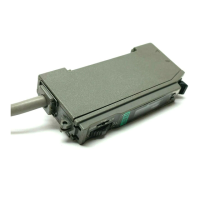
Describes the sensor's compatibility with DIN rail mounting using an optional bracket.
Highlights the sensor's fast response time of 2 ms or less with chattering prevention.
Explains the availability of an analog bar display for indicating pressure changes.
Introduces the availability of a ±100 kPa compound pressure type sensor.
Details the function for storing and recalling two patterns of set values.
Discusses the sensor's ability to control outputs using four different modes.
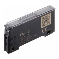
Lists available connector options and their specifications.
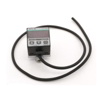
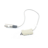
Details the available cables with attached connectors, including lengths.
Describes the optional bracket for mounting the sensor on a 35 mm DIN rail.
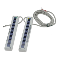
Introduces available brackets for vertical and horizontal sensor mounting.
Explains the bracket for attaching sensors laterally on a panel.
Provides the I/O circuit diagram and pin position for NPN output type sensors.
Provides the I/O circuit diagram and pin position for PNP output type sensors.
Details the operational procedures, including key-protect and window comparator mode.
Explains the functions of the LCD display and the keys used for operation.
Outlines the conditions required for CE conformity, particularly regarding wiring.
Lists potential error messages and their corresponding corrective actions.
Provides essential guidelines for safe and effective wiring of the sensor.
Covers general precautions related to usage, environment, and handling.
Details the step-by-step procedures for sensor setting, including zero-point adjustment.
Explains how to use the forced output mode for checking sensor operation.
Describes the function for storing and recalling multiple set values.
Details functions for displaying maximum and minimum pressure values.
Explains how to set and release the key-protect function to prevent changes.
Provides instructions and torque specifications for connecting fittings to the pressure port.
Details the installation procedure for the panel mounting bracket.
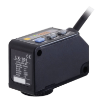
Shows the overall dimensions and key features of the DP4-5 sensor.
Illustrates the dimensions and mounting options for the DIN rail bracket.
Provides dimensions and cut-out details for the panel mounting bracket.
Shows dimensions and panel cut-out for the multi-panel mounting bracket.
Details the dimensions for the vertical sensor mounting bracket.
Details the dimensions for the horizontal sensor mounting bracket.
Illustrates the dimensions of the CN-63 connector and attached cables.
Explains the use of the LCD bar for displaying pressure changes.
Describes the function for storing two types of set values for quick changes.
Details how to set hysteresis for comparative output ON/OFF control.
Explains how comparative output turns ON/OFF within a set pressure range.
Describes the mode where output is forcibly maintained at OFF level.
Explains automatic setting of pressure values using actual objects.
Procedure for adjusting the displayed pressure to zero when the port is open.
Setting the display mode, output mode, and unit of measurement.
Setting NO/NC, display cycle, response time, and pressure range.
Details setting of output values P-1 to P-3, and P-4 to P-6.
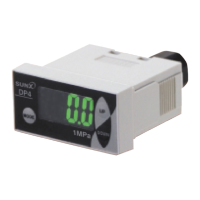
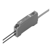
The DP4 Series is a compact digital pressure sensor designed for a wide range of applications, particularly suitable for panel mounting due to its new shape. It offers a bright, easy-to-view two-color digital display and various output modes for flexible control.
The DP4 Series functions as a pressure detection sensor, capable of measuring vacuum, positive, and compound pressures. It features a 3½ digit LCD display that shows measured pressure, settings, error messages, and key-protect status. The display changes color from green (output OFF) to red (output ON) to indicate output status at a glance.
The sensor supports four output modes:
It also incorporates a memory bank function, allowing storage of two patterns of set values (Set Values 1-3 and Set Values 4-6) for quick changes. Peak hold and bottom hold functions are available to display maximum and minimum pressure values, aiding in determining pressure variation ranges and setting references.
The DP4 Series is available in three main types:
Common Specifications:
| Brand | Sunx |
|---|---|
| Model | DP4 Series |
| Category | Accessories |
| Language | English |