.H\ORFNIXQFWLRQ
The keylock function prevents key operations so that the conditions set
in each setting mode are not inadvertently changed.
,QWKHNH\ORFNFRQGLWLRQ³ ´LVGLVSOD\HGZKHQSUHVVLQJDQ\NH\
Ɣ
Ɣ
<When in RUN mode>
[Keylock released]
Press for 2 sec. or more
Auto-
matic
Auto-
matic
<When in RUN mode>
[Keylock set]
Press for 2 sec.
Automatic
6(77,1*02'(
6
Emission
frequency 0
Emission
frequency 1
<Setting mode>
<Output operation setting mode>
(Light-ON)(Dark-ON)
<Emission amount setting mode>
<Teaching mode>
For details, refer to “
TEACHING MODE.”
7
<Timer operation setting mode>
<Emission frequency setting mode (Note 2)>
(Without timer)
(Timer delay) (Timer delay)
<Timer delays setting mode>
: Select timer delays from 1ms, 5ms, 10ms, 20ms, 40ms, 50ms,
100ms, 500ms, and 1,000ms.
<Timer delays setting mode>
ON delay
timer
OFF delay
timer
Automatic
<RUN mode>
Press for 2 sec.
<RUN mode>
In case of FX-101Ƒ In case of FX-102Ƒ
In case of FX-101Ƒ
: Select emission frequency from
“” “ ” “ ,” and “”
: Select emission frequency from
“” “” “,” and “”
In case of FX-102Ƒ
(Level 2)(Level 3) (Auto + Level 3)
(Note 1)
(Level 1)
Setting mode appears after SUHVVLQJ 02'(NH\IRUVHFLQ581
PRGH.
581PRGHDSSHDUVDIWHU02'(NH\LVSUHVVHGIRUVHFLQSURFHVVRI
VHWWLQJ+RZHYHUFKDQJHG LWHPVEHIRUH SUHVVLQJ02'( NH\IRUVHF
have been set.
Ɣ
Ɣ
Notes: 1)
:KHQVHOHFWLQJ$XWRGLVSOD\HGZLWK³ ´ SURSHU OLJKW LQWHQVLW\ ´ SURSHU OLJKW LQWHQVLW\ , proper light intensity (³ ´ ³ ´
or ³
´LV DXWRPDWLFDOO\ GHFLGHG ZKHQ RQO\ WKH OLPLW WHDFKLQJ LV VHW is automatically decided when only the limit teaching is set. ((³ ´LV
indicated at first selecting.)
In Auto, emission amount is automatically set to let the incident light intensity
in proper range (1000 to 3800).
2) The operation indicator and the beam-emitting inlet blink while setting emis-
sion frequency. (When emission frequency 0 is set, they light up.) The blink-
ing cycle depends on each emission frequency.
(PLVVLRQIUHTXHQF\IDVWļ(PLVVLRQIUHTXHQF\VORZ
Setting item
)DFWRU\VHWWLQJ
'HVFULSWLRQ
Teaching
mode
Threshold value can be set in 2-point teaching, limit
teaching or full-auto teaching.
)RUGHWDLOVUHIHUWR³
7($&+,1*02'(´
Output operation
setting mode
/LJKW21RU'DUN21FDQEHVHW
Timer operation
setting mode
:LWKRXWWLPHU21GHOD\WLPHURU2))GHOD\WLPHUFDQEH
set.
Timer delays
setting mode
:KHQVHWWLQJ21GHOD\WLPHURU 2)) GHOD\WLPHULQWKH
timer operation setting mode, timer delays can be set.
When timer is not set, this mode is not displayed.
,QFDVHRIOLPLWWHDFKLQJ
This is the method of setting the threshold value by teaching only the ob-
MHFWDEVHQWFRQGLWLRQVWDEOHLQFLGHQWOLJKWFRQGLWLRQ7KLVLVXVHGIRUGHWHF-
WLRQLQWKHSUHVHQFHRIDEDFNJURXQGERG\RUIRUGHWHFWLRQRIVPDOOREMHFWV
:KHQVHOHFWLQJ³$XWR´GLVSOD\HGZLWK³ ´LQWKHHPLVVLRQDPRXQWVHW-
WLQJPRGHSURSHUOLJKWLQWHQVLW\FDQEHDXWRPDWLFDOO\VHW)RUWKHVHWWLQJ
PHWKRGUHIHUWR³
6(77,1*02'(´
Ɣ
Ɣ
<Teaching mode>
or
ƒ3UHVV2))NH\WKHWKUHVKROGYDOXHLVVKLIWHGWRORZHUVLGHWZLFH
ZKHQXVLQJWKUXEHDPW\SHILEHUDQGSUHVV21NH\WKHWKUHVKROG
YDOXHLVVKLIWHGWRKLJKHU
VLGHWZLFHZKHQXVLQJ
UHIOHFWLYHW\SHILEHU
7KUXEHDPW\SH 5HIOHFWLYHW\SH
%DFN
JURXQG
$XWRPDWLF
or
$XWRPDWLF
ƒ
7KHSUHVHQWLQFLGHQWOLJKWLQWHQVLW\EOLQNVLQUHGDWWKHGLJLWDOGLVSOD\
ƒ3UHVV21NH\RU2))NH\ZKLFKLVSUHVVHGLQWKHSUHYLRXVVWHS
)RUH[DPSOHZKHQ21NH\LVSUHVVHGLQWKHSUHYLRXVVWHSSUHVV
21NH\DJDLQIRUWKHVHFRQGWLPH
7KHLQFLGHQWOLJKWLQWHQVLW\DWWKHVHFRQGNH\LQSXWLVQRWUHODWHGWRWKH
WKUHVKROGYDOXH
ƒ7KHVHWWLQJLVGRQH
3UHVV
7KUHVKROG
YDOXH
High
/RZ
7KUHVKROGYDOXH
7KUHVKROGYDOXH
3UHVV
15%
15%
,QFLGHQWOLJKWLQWHQVLW\
ZLWKREMHFWDEVHQW
ƒ7KHVHWWKUHVKROGYDOXHLVLQGLFDWHGRQWKHJUHHQGLJLWDOGLVSOD\
7KHWKUHVKROGYDOXHGHSHQGVRQWKHVKLIWDPRXQW)RUVHWWLQJPHWKRG
RIWKHVKLIWDPRXQWUHIHUWR6KLIWVHWWLQJPRGH!LQ³PRO MODE´
ƒ0DUJLQIRUWKHWKUHVKROGYDOXH
WRWKHLQFLGHQWOLJKWLQWHQVLW\LV
LQGLFDWHGRQWKHUHGGLJLWDO
GLVSOD\
:KHQWKHPDUJLQLV
RUPRUH³´LV
GLVSOD\HG
8
ƒ5HIHUHQFHLQFLGHQWOLJKWLQWHQVLW\LVVHWE\WKHILUVWNH\LQSXWDQG
LQGLFDWHGRQWKHJUHHQGLJLWDOGLVSOD\
&DQFHOODWLRQRIWKHVHWWLQJIRUWKHUHIHUHQFHLQFLGHQWOLJKWLQWHQVLW\LV
SRVVLEOHZKHQ02'(NH\LVSUHVVHG
7($&+,1*02'(
7
Make sure that detection may become unstable if less margin is applied in
the use environment when teaching.
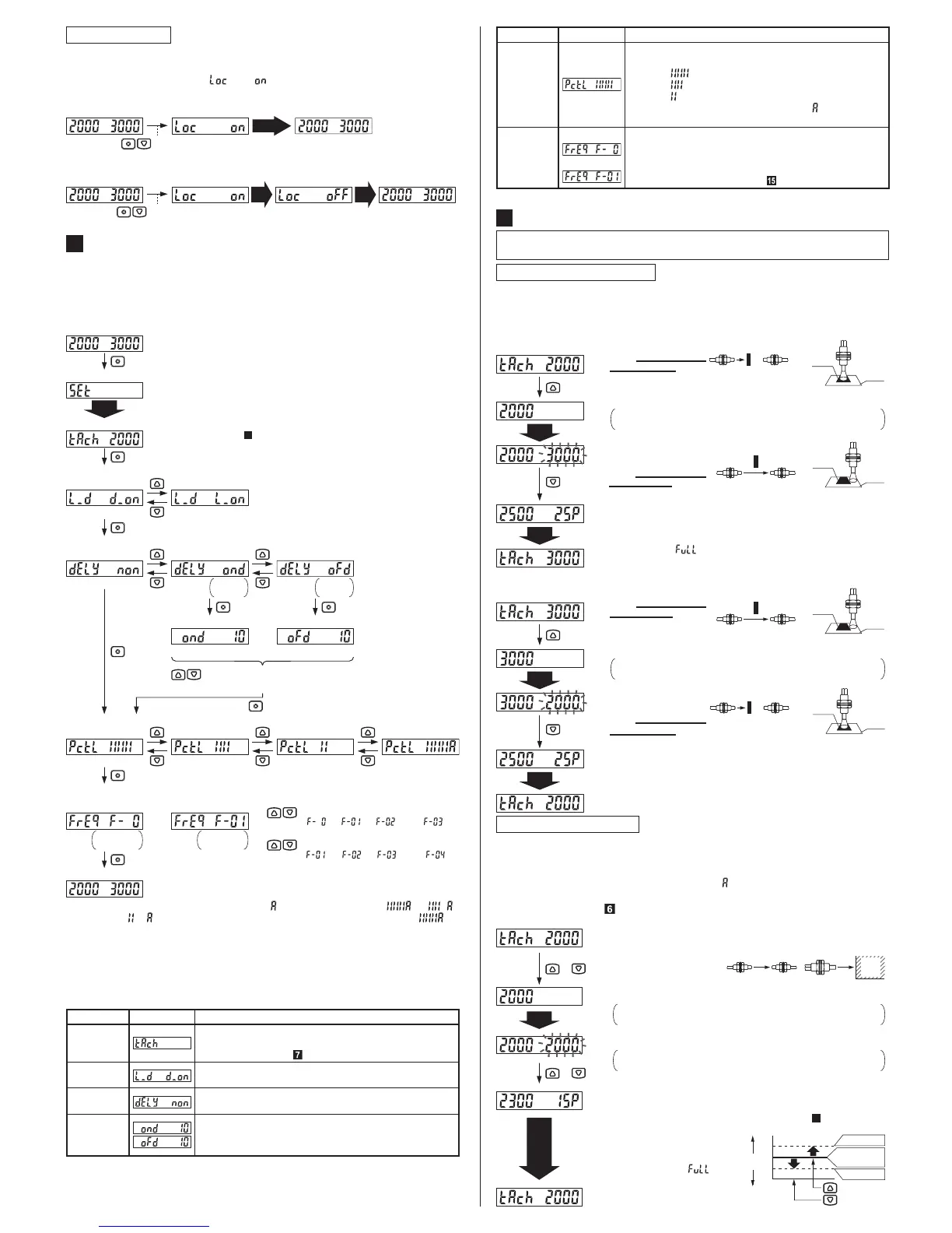
,QFDVHRISRLQWWHDFKLQJ
This is the method of setting the threshold value by teaching two points, corresponding
WRREMHFWSUHVHQWDQGREMHFWDEVHQWFRQGLWLRQV1RUPDOO\VHWWLQJLVGRQHE\WKLVPHWKRG
7KHRXWSXWRSHUDWLRQVHWWLQJRI/LJKW21RU'DUN21LVUHÀHFWHGDXWRPDWLFDOO\
Ɣ
Ɣ
[For output ON when in object absent condition]
Automatic
<Teaching mode>
Thru-beam type
Light interrupted
condition
Light received condition
Mark
Reflective type
Base
Automatic
Automatic
<Teaching mode>
[For output ON when in object present condition]
Thru-beam type
Light received condition
Light interrupted condition
Mark
Reflective type
Base
Automatic
ƒ
The setting is done.
ƒ
The threshold value which is set between the first and the second
incident light intensity is indicated on the green digital display.
ƒ0DUJLQIRUWKHWKUHVKROGYDOXHWRWKHILUVWRUWKHVHFRQGLQFLGHQWOLJKW
intensity is indicated on the red digital display.
ƒ3UHVV21NH\LQREMHFW
absent condition.
ƒ
The present incident light
intensity blinks in red at
the digital display.
ƒ3UHVV2))NH\LQREMHFW
present condition.
ƒ
The setting is done.
ƒ3UHVV21NH\LQREMHFW
present condition.
Thru-beam type
Light interrupted
condition
Light received condition
Mark
Reflective type
Base
Thru-beam type
Light received condition
Light interrupted condition
Mark
Reflective type
Base
ƒ
The present incident light
intensity blinks in red at
the digital display.
ƒ3UHVV2))NH\LQREMHFW
absent condition.
ƒ
The threshold value which is set between the first and the second
incident light intensity is indicated on the green digital display.
ƒ
Margin for the threshold value to the first or the second incident light
intensity is indicated on the red digital display. When the margin is
200% or more, “ ” is displayed.
ƒ
The first incident light intensity is set and indicated on the green digital display.
Cancellation of the setting for the first incident light intensity is
SRVVLEOHZKHQ02'(NH\LVSUHVVHG
ƒ
The first incident light intensity is set and indicated on the green digital display.
Cancellation of the setting for the first incident light intensity is
SRVVLEOHZKHQ02'(NH\LVSUHVVHG

 Loading...