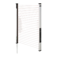
SF2-A
457
PRECAUTIONS FOR PROPER USE
LIGHT CURTAINS
FOR SAFEGUARD
SF4-AH
Light Curtain
SF2-A
SF2-NSF2-EHSF-AC
Safety Relay Unit
Sensing area
• Make sure to install this product such that any part of
the human body that passes through the sensing area
is detected before it reaches dangerous machine parts.
If the human body is not detected, there is a danger of
serious injury or death.
• Do not use any reflective type or retroreflective type
arrangement.
For use in U.S.A. (as per ANSI B11.19)
• Equation 2 D
K(TsTcTSF2Tbm)Dpf
• D: Safety distance (mm)
Minimum required distance between the surface of the sensing
area and dangerous part of machine.
• K:
Intrusion speed {Recommended value in OSHA is 63 (inch/sec.)
[c1,600 (mm/sec.)]}
ANSI B11.19 does not define the intrusion speed (K). When
determining K, consider possible factors including physical
ability of operators.
• Ts: Halt time calculated from the operation time of the control
element (air valve, etc.) (sec.)
• Tc: Maximum response time of the control circuit required for the
brake to function. (sec.)
• TSF2: Response time of the SF2-A series 0.015 (sec.)
• Tbm: Additional halt time tolerance for the brake monitor (sec.)
TbmTa(TsTc)
Ta: Setting time of brake monitor (sec.)
When the machine is not equipped with a break monitor, it is
recommended that 20 % or more of (Ts Tc) is taken as
additional halting time.
• Dpf: Additional distance calculated from the size of the minimum
sensing object of the sensor (mm)
SF2-AH(-PN)(-H) Dpf78.2 mm 3.079 in,
SF2-AA(-PN)(-H) Dpf146.2 mm 5.756 in
Dpf3.4(d0.276) (inch)
Dpf3.4(d7) (mm)
d: Minimum sensing object diameter 1.2 (inch) c30 (mm)
SF2-AH(-PN)(-H)
Minimum sensing object diameter 2.0 (inch) c 50 (mm)
SF2-AA(-PN)(-H)
Note that the value of Dpf is not less than or equal to 0.
Influence of reflective surface
Install the sensor by considering the effect of nearby
reflective surfaces and taking suitable countermeasures.
Failure to do so may cause the sensor not to detect,
resulting in serious injury or death.
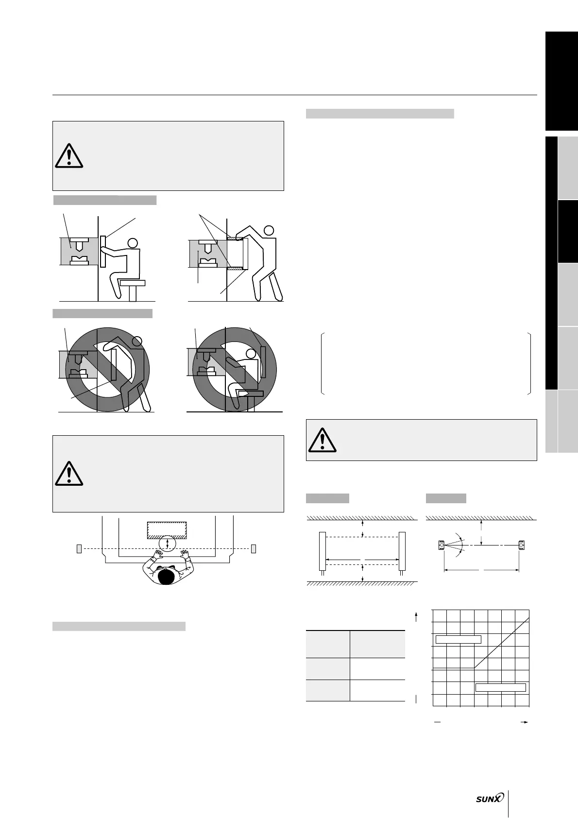
• Keep the minimum distance given below, between the sensor and
a reflective surface.
Reflective ceiling Reflective surface
Reflective floor
Emitter
Receiver
Emitter
(Note)
Receiver
Sensing area
6
6
D
D
L
D
L
Side view Top view
0
1
3.281
3
9.843
5
16.404
7
22.966
0.2
0.656
0.4
1.312
0.6
1.969
0.8
2.625
0.1
0.328
0.3
0.984
0.5
1.640
0.7
2.297
Allowed setting distance D (m ft)
Distance between emitter and receiver L (m ft)
2
6.562
4
13.123
6
19.685
Allowed setting area
Unallowed setting area
Note: The effective aperture angle for this sensor is 5 (with L 3m
9.843 ft) as required by IEC 61496-2 / UL 61496-2. However, install
this sensor away from the reflective surfaces, assuming an effective
aperture angle of
6 to provide for misalignment, etc., during
installation.
0.3 to 3 m
0.984 to 9.843 ft
3 to 7 m
9.843 to 22.966 ft
0.31 m 1.017 ft
Ltan$$6
L0.105 (m) 0.344 (ft)
Distance
between emitter
and receiver, L
Allowed
setting
distance, D
Refer to p.1135 l for general precaution.
Correct mounting method
Dangerous part
Sensing area
Protective
structure
Dangerous part
Sensing area
Sensing area
Dangerous part
Dangerous part
Sensing
area
Wrong mounting method
Safety distance
•
Calculate the safety distance correctly, and always
maintain a distance which is equal to or greater than the
safety distance, between the sensing area of this sensor
and the dangerous parts of the machinery. If the safety
distance is miscalculated or if sufficient distance is not
maintained, there is a danger of serious injury or death.
•
Before designing the system, refer to the relevant standards of the
region where this device is to be used and then install this device.
Emitter
Receiver
Beam axis
D
Dangerous part
of machine
•
Safety distance is calculated based on the following equation when a person
moves perpendicular (normal intrusion) to the sensing area of the sensor.
(Please check the latest standards for the equation.)
For use in Europe (as per EN 999)
• Equation 1 D
KTC
D: Safety distance (mm)
Minimum required distance between the surface of the sensing
area and dangerous part of machine.
K: Intrusion speed of operator’s body or objects (mm/sec.)
Normally, taken as SF2-AH(-PN)(-H) 2,000 (mm/sec.),
SF2-AA(-PN)(-H) 1,600 (mm/sec.) for calculation.
T: Response time of total equipment (sec.)
T
TmTSF2
Tm: Maximum halt time of device (sec.)
TSF2: Response time of the SF2-A series 0.015 (sec.)
C: Additional distance calculated from the size of the minimum
sensing object of the sensor (mm)
Note that the value of C is not less than or equal to 0.
C8(d14)
d: Minimum sensing object diameter
SF2-AH(-PN)(-H) 30 (mm) 1.181 (in)
For SF2-AA(-PN)(-H), C
850 (mm) 33.465 (in) (constant)
Ramco Innovations - 1207 Maple Street, West Des Moines IA USA 50265 - 800-280-6933 - www.ramcoinnovations.com


 To Next Page
 Loading...