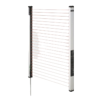
SF2-A
458
PRECAUTIONS FOR PROPER USE
LIGHT CURTAINS
FOR SAFEGUARD
SF4-AH
Light Curtain
SF2-A
SF2-N
SF2-EH
SF-AC
Safety Relay Unit
Mounting
• The minimum bending radius of the cable is R30 mm R1.181 in.
Mount the sensor considering the cable bending radius.
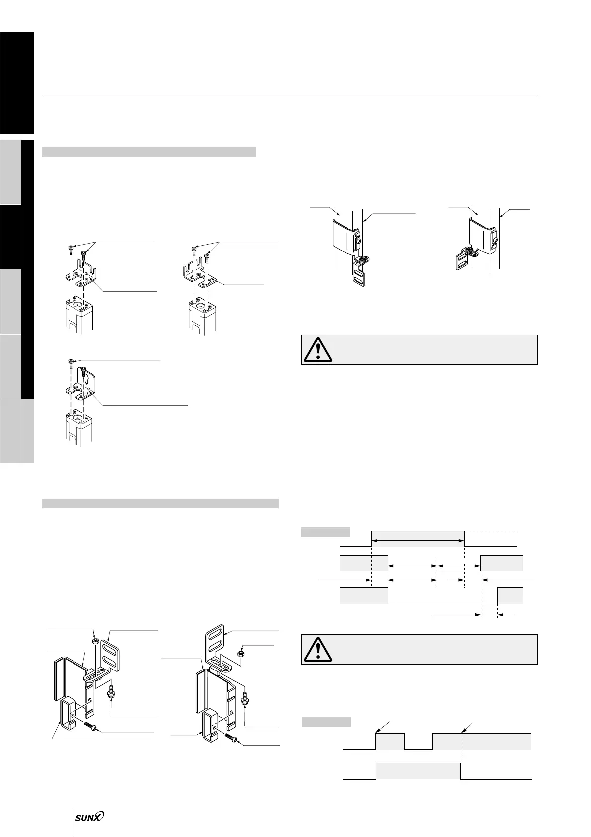
Mounting of sensor mounting bracket (MS-SF2N-1/3/5)
Mounting of intermediate supporting bracket (MS-SF2N-2/4, MS-SF4A-H2/H4)
• Choose the sensor mounting bracket based on the mounting
direction (side or rear), and temporarily tighten the brackets with
two M3 (length 5 mm 0.197 in) hexagon-socket-head bolts for
adjusting the mounting angle. After the beam-axis alignment,
tighten then bolts completely. When mounting the sensor, the
tightening torque should be 0.6 N m or less.
<Side mounting><Back mounting>
Hexagon-socket-head bolts
(Accessory for MS-SF2N-1)
(Accessory for MS-SF2N-1)
Rear mounting
bracket MS-SF2N-1
Side
mounting
bracket
MS-SF2N-3
Hexagon-socket-head bolts
(Accessory for sensor)
(Optional)
<Center sensor mounting bracket>
Hexagon-socket-head bolts
(Accessory for MS-SF2N-1)
Center sensor
mounting bracket
MS-SF2N-5
(Optional)
Note: Multiple beam channel sensors requiring the intermediate supporting
bracket (20 mm 0.787 in beam pitch type: 36 beam channels or more,
40 mm 1.575 in beam pitch type: 18 beam channels or more) cannot
be mounted on an aluminum frame with the center sensor mounting
bracket (MS-SF2N-5).
1
Place the retaining plate on the U-shaped rear / side supporting
bracket and temporarily tighten them with an M3 (length 10 mm
0.394 in) pan head screw.
2
Temporarily tighten the L-shaped intermediate supporting
bracket to the U-shaped rear / side supporting bracket with an
M4 (length 10 mm 0.394 in) hexagon-socket-head bolt.
2
2
1
1
2
2
1
1
<Back mounting><Side mounting>
MS-SF2N-2 / MS-SF4A-H2
U-shaped rear supporting bracket,
retaining plate
MS-SF2N-4 / MS-SF4A-H4
U-shaped side supporting bracket,
retaining plate
Hexagon nut
U-shaped rear
supporting bracket
L-shaped intermediate
supporting bracket
Hexagon nut
U-shaped side
supporting bracket
L-shaped intermediate
supporting bracket
(MS-SF2N-L)
(MS-SF2N-L)
(Accessory for MS-SF2N-L)
Accessory for
MS-SF2N-L
(
(
(
(
(
(
M4 hexagon-
socket-head bolt
Retaining plate
M4 hexagon-
socket-
head bolt
Retaining
plate
M3 pan head screw
M3 pan head
screw
(Accessory for MS-SF2N-L)
(Accessory for MS-SF2N-L)
(Accessory for MS-SF2N-L)
(Accessory for MS-SF2N-L)
Note: The above figures are only applicable to the MS-SF2N-2/4.
The MS-SF4A-H2/H4 have different shapes.
3
Clamp the sensor main body with the U-shaped rear / side
supporting bracket and completely tighten the M3 pan head screw
that secures the retaining plate. (Tightening torque: 0.4 N m or less)
After the beam-axis alignment, ensure that the M4 hexagon-socket-
head bolt, which was used to temporarily attach the
L-shaped intermediate supporting bracket to the U-shaped rear /
side supporting bracket, is now fully tightened. (Tightening torque:
1.8 N m or less)
<Back mounting><Side mounting>
Sensing surface
Sensor
Sensing
surface
Sensor
Note: The above figures show how to mount the emitter onto the intermediate
supporting brackets. Note that the top and bottom orientation will be
reversed when mounting the receiver to the supporting brackets.
Test input (self-diagnosis function) / Emission halt function
In order to maintain safety, carry out the self-diagnosis at
least once a day.
• If the test input wire is made open for 45 ms or more, or
connected to Vs1.5 V to Vs (PNP output type: 0 to1.5 V)
detailed diagnosis, in addition to the internal self-diagnosis being
done during normal operation, is carried out. In case no
abnormality is discovered during self-diagnosis, and if the test
input is continued to be kept open after that, emission halt state is
achieved. In case an abnormality is discovered during self-
diagnosis, the device is put in the lockout state at that instant, and
the control output (OSSD) and alarm outputs are fixed at the OFF
state.
• Emission halt state is achieved when no abnormality is detected
during self-diagnosis and the test input is continued to be kept
open after that. During emission halt, control output (OSSD) and
alarm output switch to the OFF state. By using this function,
malfunction due to extraneous noise, or abnormality in control
output (OSSD) and alarm output, can be determined even from
the equipment side.
Control output
(OSSD)
ON
OFF
Open
Close
45 ms or more
45 ms max.
40 to 60 ms
Self-diagnosis
45 ms max.
150 ms max.
Input signal
Operation
state
Emission halt
ON
OFF
ON
OFF
Control
output
(OSSD)
Alarm
output
Beam
interrupted
Control output (OSSD)
short-circuit
Starting emission
Be sure to use the alarm output.
• Since the occurrence of a fault, such as that due to an external
short-circuit, cannot be conveyed to the equipment side by control
output (OSSD), the alarm output generates a warning signal.
Design a system such that the equipment can be stopped when
either control output (OSSD) or alarm output is output.
Time chart
Time chart
Alarm output
Refer to p.1135 l for general precaution.
Ramco Innovations - 1207 Maple Street, West Des Moines IA USA 50265 - 800-280-6933 - www.ramcoinnovations.com


 To Next Page
 Loading...