3
1. Steering switch: Control the dolly to move "forward" or "backward"
2. Speed regulating switch: Adjust the running speed of the dolly
3. Connecting rod: Connect the handle and the bracket
4. Power switch: "Turn on" or "Turn off" the power supply of the dolly. Please turn off the power
supply when not in operation
5. Battery case: With battery and controller placed inside
6. Hitch ball: Connect the towed vehicle with cover
7. Adjusting lever: Adjust the forward, backward, upward and downward positions of the ball
head
8. Pin: Lock the adjusting lever
9. Controller: Device to preset instruction
10. Battery pack: Two 12V 7AH lead-acid batteries
11. Rear wheel: Transmit traction force
12. Rear axle motor: Power supply source
13. Swivel wheel: Realize the change of direction
14. Bracket: Fix battery case and rear axle motor
15. Charger: INPUT 100~240VAC, OUTPUT 28.8VDC - 2.0A
16. DC charger socket: Connect the charger
17. Handle bar: Install the control switch
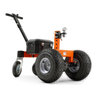
ASSEMBLY
Figure 1
1
2
4
3
Wire
1. Assemble handle bar
Insert the connecting rod into the handle
bar assembly, and thread the wire out from
the end of the connecting rod (Step 1);
Insert M10x55 bolt in alignment with the
hole (Step 2); Tighten M10 nut (Step 3);
Tighten M10x16 hexagon bolt (Step 4).
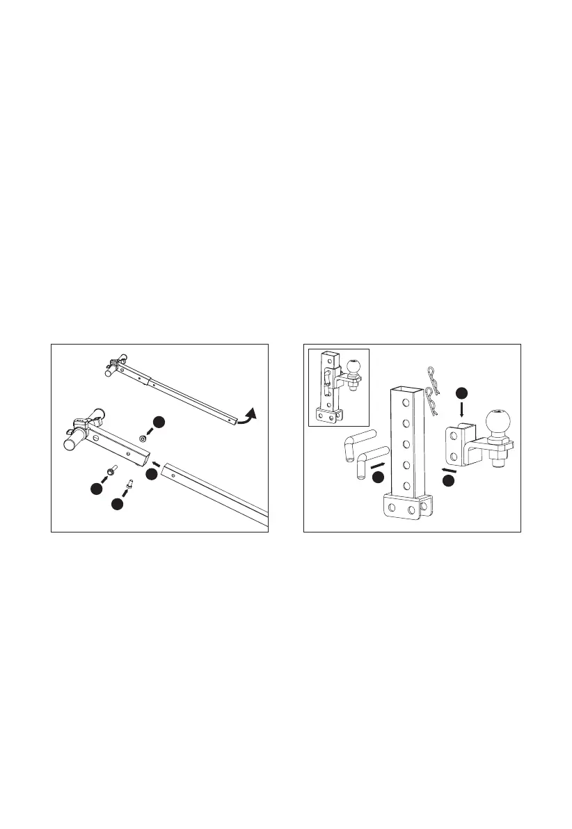
2. Assemble hitch ball
Align the groove of the ball head assembly
with the adjusting lever and select the
appropriate hole position (Step 1); Insert
two bolts (Step 2); Insert two B-pins for
fixing (Step 3).
2
1
3
Figure 2