MG & SG Series Boilers – Installation and Service Manual
15
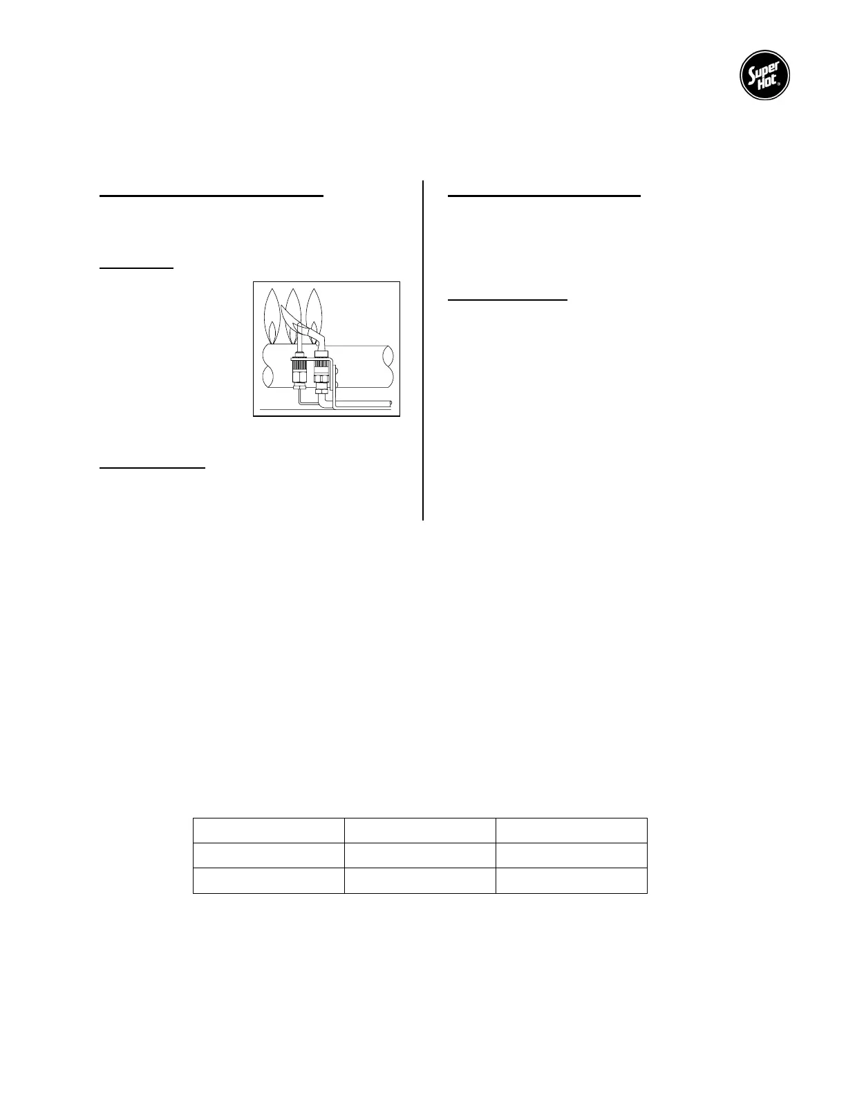
FIGURE 2 - PILOT FLAME
ADJUSTMENT
3.3 CHECK BURNER SYSTEM
To maintain safe and efficient operation, examine the burner system regularly through the inspection hole
near the pilot tube.
Check condition of burner system
It is possible for parts of the burners system to
become plugged, cracked, eroded and/or
dislodged resulting in unsafe operation.
Pilot Flame
Remove cap screw
cover on gas valve,
then adjust gas flow to
the point where the
thermocouple tip or
sensor rod is
completely enveloped
by the flame (Figure 2),
but not necessarily
glowing red. Replace
and tighten cap.
Check for lifting
Flames should not lift excessively from the
burner ports. The flames may lift slightly during
ignition or when the burners are cold.
Check ignition and extinction
Ignition should flow quickly and smoothly across
all the burners. Popping noises or explosions
from the burners during ignition, extinction or
normal burner operation indicates the need for
service.
Check flame color
An extremely yellow flame, as seen on a burning
candle or match, is an indication of incomplete
combustion and is usually accompanied by the
formation of soot and carbon monoxide (carbon
monoxide is a lethal, colorless and odorless
gas). If soot is allowed to accumulate, it will
partially restrict free passage of products of
combustion to the flue. Under typically
operating conditions, the flame should have a
distinct bright blue inner cone and a blue/orange
outer cone.
If any of the above problems are observed or the burner system does not operate properly,
immediately take corrective measures.
3.4 AQUASTAT ADJUSTMENT
The factory mounted aquastat controls main burner firing by sensing outlet water temperature. To set the
temperature of this control, adjust the dial until indicator points to the temperature (setpoint) at which the
gas valve will close. The gas valve will open at setpoint less the differential. The automatic reset safety
high-limit aquastat is either fixed or, if adjustable, should be set a minimum of 20°F (10°C) above the
setting of the aquastat.
3.5 GAS MANIFOLD PRESSURE
The designated manifold pressures are as shown in the table below. A 1/8” NPT tapping is provided on
the manifold or gas valve for connecting a manometer to check this pressure. Both natural gas and
propane models are furnished with gas valves which have a built in gas pressure regulator. If necessary,
adjust to the proper value by removing cap and turning adjusting screw clockwise to increase manifold
pressure or counterclockwise to decrease manifold pressure.
Model Natural Gas Propane
MG
3.5” W.C. 11.0” W.C.
SG
3.5” W.C. 10.0” W.C.

 Loading...