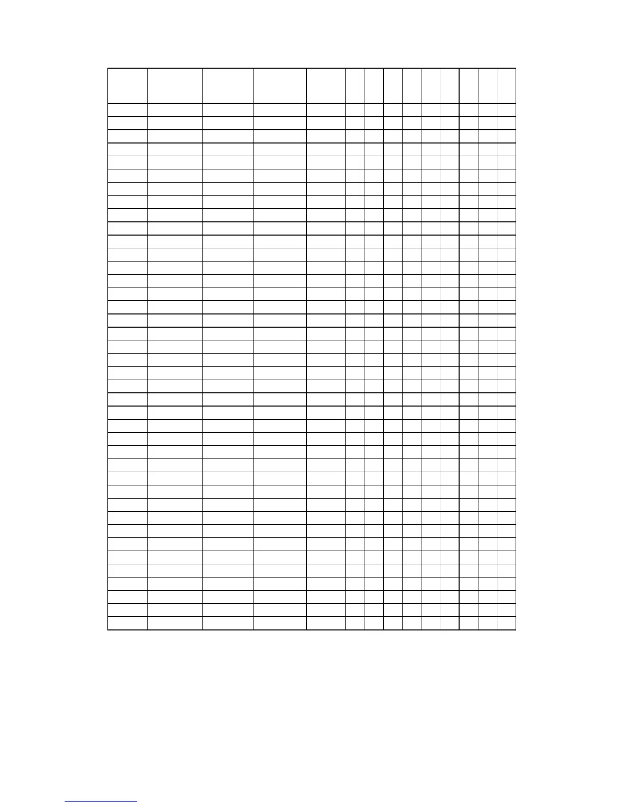
Ch. No.
Frequency
(MHz)
"N" digital
codes
VCO freq.
(MHz)
RX 1st
IF freq.
(MHz)
P0
P1
P2
P3
P4
P5
P6
P7
P8
1
26.965
330
17.18
37.66
0
1
0
1
0
0
1
0
1
2
26.975 329 17.19 37.67 1 0 0 1 0 0 1 0 1
3
26.985 328 17.20 37.68 0 0 0 1 0 0 1 0 1
4
27.005 326 17.22 37.70 0 1 1 0 0 0 1 0 1
5
27.015 325 17.23 37.71 1 0 1 0 0 0 1 0 1
6
27.025 324 17.24 37.72 0 0 1 0 0 0 1 0 1
7
27.035
323
17.25
37.73
1
1
0
0
0
0
1
0
1
8
27.055 321 17.27 37.75 1 0 0 0 0 0 1 0 1
9
27.065 320 17.28 37.76 0 0 0 0 0 0 1 0 1
10
27.075 319 17.29 37.77 1 1 1 1 1 1 0 0 1
11
27.085 318 17.30 37.78 0 1 1 1 1 1 0 0 1
12
27.105 316 17.32 37.80 0 0 1 1 1 1 0 0 1
13
27.115
315
17.33
37.81
1
1
0
1
1
1
0
0
1
14
27.125 314 17.34 37.82 0 1 0 1 1 1 0 0 1
15
27.135 313 17.35 37.83 1 0 0 1 1 1 0 0 1
16
27.155 311 17.37 37.85 1 1 1 0 1 1 0 0 1
17
27.165 310 17.38 37.86 0 1 1 0 1 1 0 0 1
18
27.175 309 17.39 37.87 1 0 1 0 1 1 0 0 1
19
27.185 308 17.40 37.88 0 0 1 0 1 1 0 0 1
20
27.005 306 17.42 37.90 0 1 0 0 1 1 0 0 1
21
27.215 305 17.43 37.91 1 0 0 0 1 1 0 0 1
22
27.225 304 17.44 37.92 0 0 0 0 1 1 0 0 1
23
27.255 301 17.47 37.95 1 0 1 1 0 1 0 0 1
24
27.235 303 17.45 37.93 1 1 1 1 0 1 0 0 1
25
27.245 302 17.46 37.94 0 1 1 1 0 1 0 0 1
26
27.265 300 17.48 37.96 0 0 1 1 0 1 0 0 1
27
27.275 299 17.49 37.97 1 1 0 1 0 1 0 0 1
28
27.285 298 17.50 37.98 0 1 0 1 0 1 0 0 1
29
27.295 297 17.51 37.99 1 0 0 1 0 1 0 0 1
30
27.305 296 17.52 38.00 0 0 0 1 0 1 0 0 1
31
27.315 295 17.53 38.02 1 1 1 0 0 1 0 0 1
32
27.325 294 17.54 38.03 0 1 1 0 0 1 0 0 1
33
27.335 293 17.55 38.04 1 0 1 0 0 1 0 0 1
34
27.345 292 17.56 38.05 0 0 1 0 0 1 0 0 1
35
27.355 291 17.57 38.06 1 1 0 0 0 1 0 0 1
36
27.365 290 17.58 38.07 0 1 0 0 0 1 0 0 1
37
27.375 289 17.59 38.08 1 0 0 0 0 1 0 0 1
38
27.385 288 17.60 38.09 0 0 0 0 0 1 0 0 1
39
27.395 287 17.61 38.10 1 1 1 1 1 0 0 0 1
40
27.405 286 17.62 38.00 0 1 1 1 1 0 0 0 1
From this chart you see the N-Code for Ch.l is the number "330", with the numbers progressing down
to "286" at Ch.40. This number 330 is the direct result of applying +DC voltages of about 5-10 VDC to
certain PLL IC pins while grounding certain others. Thus, two possible voltage choices, and you'll
recall that the PLL uses a digital or binary counting system instead of the decimal system people use.
In a binary number system each successive chip programming pin or "bit" (binary digit) is worth
exactly double (or half) that of the pin next to it: 1, 2, 4, 8, 16, etc. Thus each pin can be defined by its
Power-of-2. We can also call them "1's bit", "2's bit", "4's bit", etc.