Do you have a question about the Superior GHC-5000N and is the answer not in the manual?
Key instructions for installers to convey to homeowners.
Critical safety warnings regarding gas leaks and flammables.
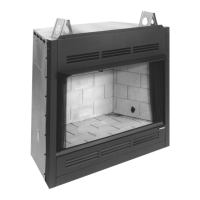
Framing requirements for fireplace enclosures.
Specifics on routing the gas line behind the face.
Securing the appliance via nailing flange.
Routing millivolt wire through access hole.
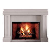
Completing the wall finish and trim around the fireplace.
Positioning internal components into the firebox.
Connecting gas supply with a flex connector and shut-off valve.
Attaching adapter fitting to the gas control valve.
Finalizing the gas line connection by shaping the flex connector.
Connecting millivolt wall switch wires to gas control valve terminals.
Safety note on operating doors fully open or closed.
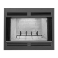
Overview of the millivolt control system components.
Ideal pilot and burner flame appearance for proper operation.
Importance of pilot flame contact with the thermopile.
Warning about high surface temperatures and burn risks.
Step-by-step guide to lighting the pilot flame.
Guidance for diagnosing and resolving issues.
Troubleshooting steps for ignitor spark issues.
Troubleshooting steps for pilot flame outage.
Troubleshooting steps for burner not igniting from pilot.
Troubleshooting steps for recurring pilot flame issues.
| Brand | Superior |
|---|---|
| Model | GHC-5000N |
| Category | Indoor Fireplace |
| Language | English |