(O
-
610
mi
I
sure and heat value of gaseous fuels. When
eiyh
iie~ation D+rarisg
Thisunithas beentested forinstallationai high
altitudes inaccordance with Canadian test s:w-
dard CANJCGA-2.17.
installing this unit at high altitudes. the rated
inout will be lower than that at sea level. The
"
-"""
,
lowered oxyoen content in the air and lowered
/
I~rooane
I
I
&7i
I
1
10-610~lI
A"
sna
6'ientlng Conrfgura!!on
gas densitiequire installation of a different
orifice toachieve efficient, clean combustion at
the burner assembly. Refer to the
foilowlng~
chart and Figure 28 andlor the rating plate on
the appliance for proper orifice size.
Order and install the appropriate high altitude
orifice kit pertheorificechari. Besuretoattach
theconversionstickertothe rating plate on the
appliance.
Gas
Type
U.S.
per ANSI 2223.1-1992
Canada per CANJCGA
2.1
7-M91
*It
Orf.
Kit
-
5ri!ice
Size
$31
Step
30.
Log Installation -The logs and em-
bers kit are packaged in
a
carton packed inside
the firebox. Remove the ceramic fiber coals
from their packaging and spread across the
front burner ports.
Elevation
0
-
2000'
Carefully position and centerthe fiber log
sonto
Orllice
the burner with the longer iog in front and the
shorter
loo all the wav to the back of the
fireplace.
iace the three
(3)
smallerfiber logs
across the two
(2)
lower logs in the manner
illustrated
(Fioure 29). Positionlno Dins on the
Figure
28
rand
2"
Venting Configuration
Elevation
0
-
2000'
Theappiiance is shipped from the factory with
the standard
3'
and
2'
(natural or propane)
#53
(.0595)
orlfice installed. If the appliance is to be in:
stalled with the opttonal
4'
and
6'
venting,
remove and replace the standard orifice with
the appropriate (natural or propane) orifice
provided in the
4"
and
6'
chimney kit. Refer to
Figure28and the following chart.
Figure
29
PIN
064202
1
NOTE. DIAGRAMS
b
ILLUSTPATIONSNOT
TOSULE
2000 -4500'
(610
-
1370 m)
~oweriogs~nd;cateto~~o~ location:
he
flames
should not impinge on the logs.
Install the top logs beginning with the left log
first. Move the back lower !og ieft or right as
necessaly to align the positioning pins. Once
this log is in place, make sure the rear log is
upright and ail the way to
the back of the flat
surface of
the burner pan assembly.
Place the right
iug
on the set, again adjusting
the lower log
left or right as necessary to align
the positioning pins.
Place the top
cen!er log in piace by mounting
the
left side of this lag first: then position the
right side of this log on the positioning pin.
The installation of the
logsshould becomplete
and resemble Figure
29.
Step
31.
Checking the System -Afterthe gas
line is installed,
logsarein placeand ihesystem
is leak checked,
run.intial system checkout
before closing up the front of the unit. Follow
the pilot lighting instructions on page 18.
Hote:Instructionsarealso
foundon thepullout
panel located on the
bottom surface of the
appiiance.
Note:
The doorswitch
must
be held closed for
burner operation when testing.
When first
lighting the appliance,
it
wiii take a
few minutes for the line to purge itself of air.
Once purging is complete, the pilot and burner
will
lightand operateas indicated intheinstruc-
tion manual. Subsequent iightings of the appli-
ance will not require such purging. Inspect the
pilotflame (remove logs, if necessary, handling
carefully)
The flame shouid be steady, not lifting or float-
ing. Flame should be blue in colorwith traces of
orange at the outer edge.
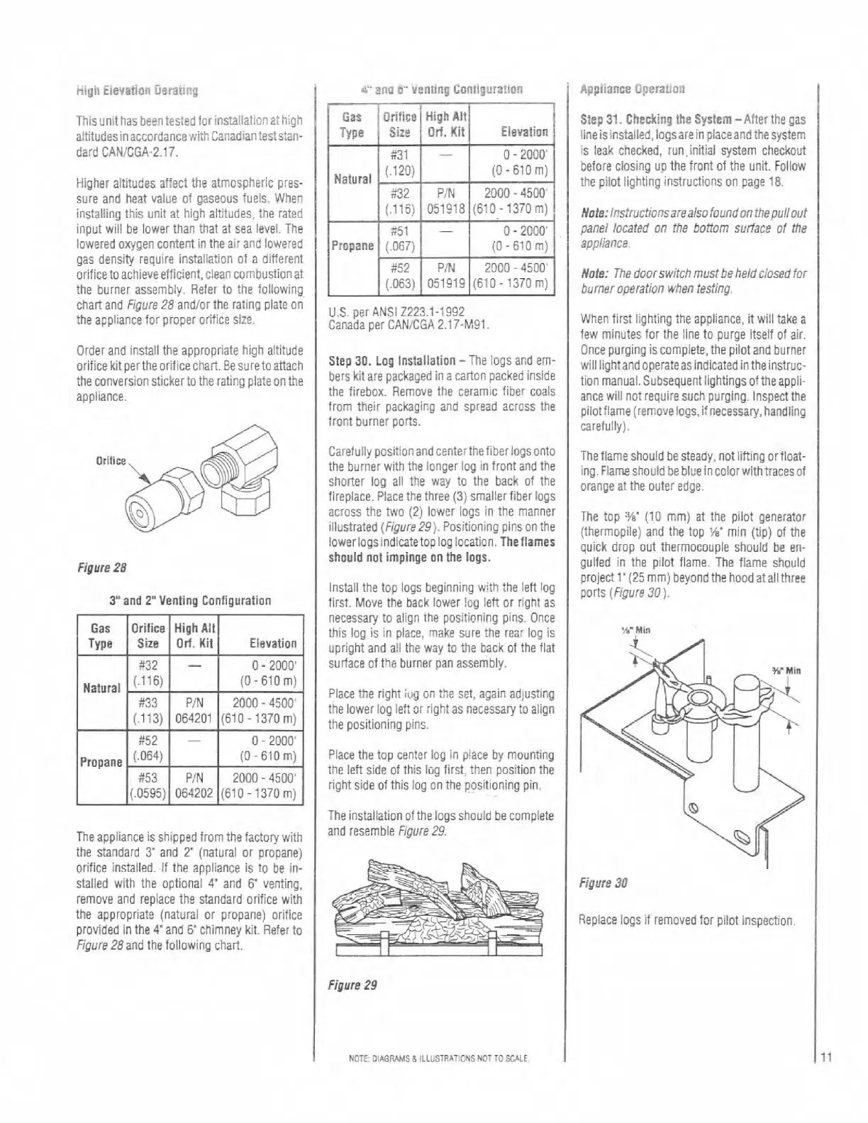
The top
3/s'
(10 mrn) at the pilot generator
(thermopile] and the top
'K
min (tip) of the
quick drop out thermocouple should be en-
gulfed in the pilot flame. The flame should
project
1'(25 mm) beyond the hoodat allthree
ports (Figure
30
).
Figure
30
Replace logs if removed for pilot inspection.