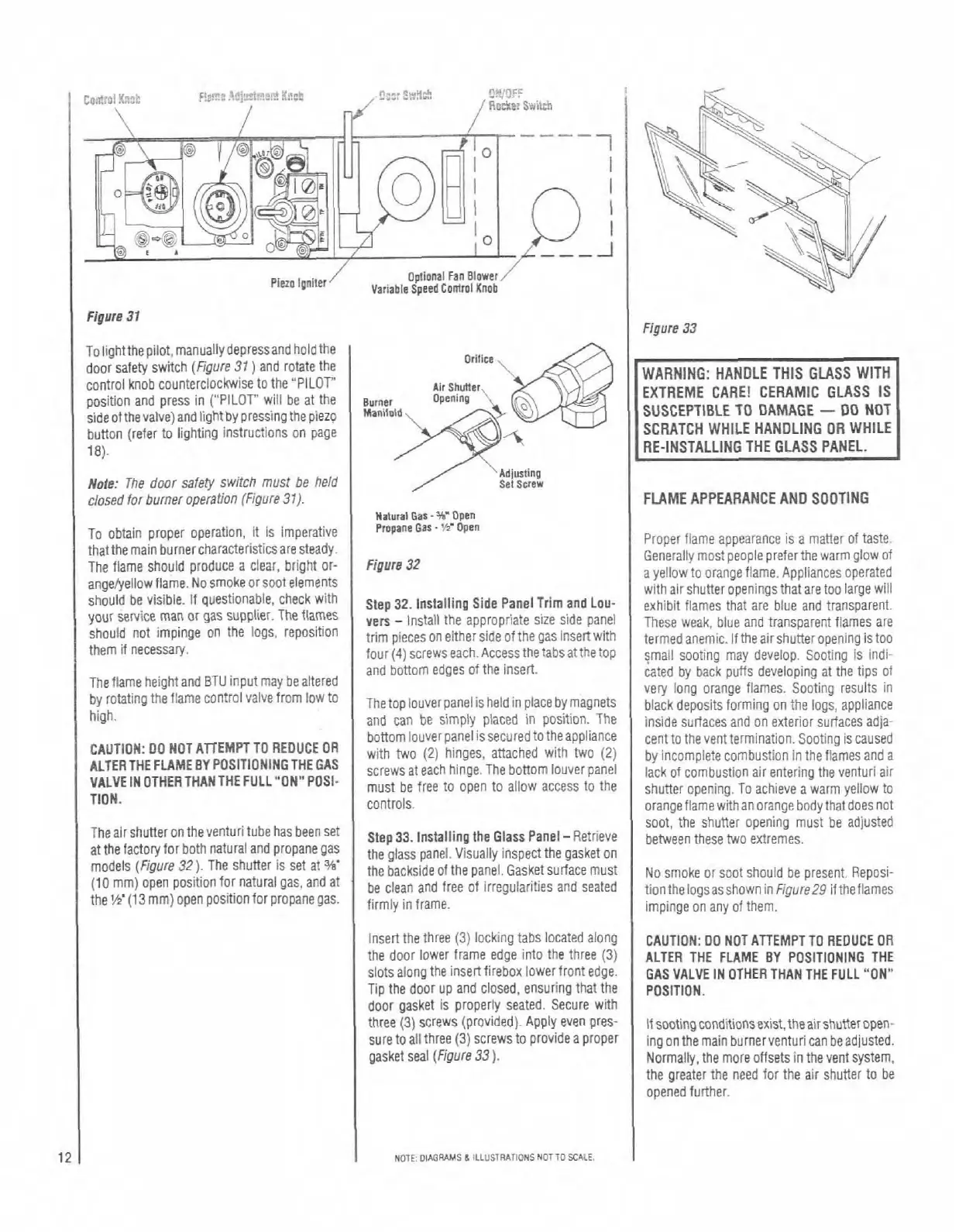
To lightthe pilot, manually depressand hold the
door safety switch
(Figure
31
)
and rotate the
controi knob counterclockwise to the "PILOT'
position and press in ("PILOT' will be at the
side olthevalve) andlightby pressing the piezp
button (refer to lighting instructions on page
18).
EXTREME CARE! CERAMIC GLASS IS
SUSCEPTIBLE TO DAMAGE
-
DO
NOT
SCRATCH WHILE HANDLING OR WHILE
I
'Adjulting
Note:
The door
safely
switch
must
be held
closed for burner ooeration (Fiaure
37
1.
I
FLAME APPEARANCE AND
soorntio
. .
.
.
To obtain proper operation, it is imperative
that the main
burnercharacteristicsare
steady.
The flame should produce a
clear, bright or-
angeiyeliowfiame. No smoke or soot elements
should be visible. If questionable, check with
your service man or gas
supplier. The flames
should not impinge on the logs, reposition
them if necessary.
The flame height and
BTU input may bealtered
by rotating the flame control valve from
low to
high.
CAUTION:
00 NOT AllEMPTTO REDUCE OR
ALTER THE
FLAMEBY POSlTlONlNGTHE GAS
VALVEINOTHERTHANTHEFULL"ONN
POSI-
TION.
The air shuner on theventuri tube has been
Set
at the factory for both natural and propane gas
models
(Figure
32).
The shuner Is set at
w'
(1
0
mm) open position for natural gas, and at
the
1s
(13
mm) open position for propane gas.
Natural
Gas-W
DP~
Propane
Gar.
'K
Open
1
Prooer fiame aooearance is a matter of taste.
vers
-
nst3i :he aPp'0prae S.ze side Pcne
ihese Aeak,
o
Le
anu traospale1.l
I
ames ale
irlnl
~IPCPS
01
e lhe'S'Ce Of:he!laS lnSprtWl!l
terllcd3neric. 'thea rshner ooel
rg
is too
lour (.l)screwse3ch ~Iccessrhet3cs31t~erop
rTa. son:
-3
ma\
dew
op scc~ nq s ,rol
Figure
32
Step
32.
Installing Side Panel Trim and Lou-
and bottom edges of the insert
~eneraily most'ieople preferthe warm glow of
a yellow to orange
flame. Appliances operated
withair shutter openings that are too large Will
exhibit flames that are
blue and transparent.
The top iouverpanel is held in place by magnets
and can be simply
piaced in position. The
bottom iouverpanel issecured to theappliance
with two
(2)
hinges, attached with two
(2)
screws at each hinge.The bottom louver panel
must be free to open to
allow access to the
controls.
Step
33.
Installing the Glass Panel
-
Retrieve
the glass panel. Visuaily inspect the gasket on
the backside
olthe panel. Gasketsurlace must
be clean and free of irregularities and seated
firmly in frame.
Insert the three
(3)
locking tabs located along
the door
lower frame edge into the three
(3)
slotsaiong the insert firebox lower front edge.
Tip the door up and closed, ensuring that the
door gasket is properly seated. Secure with
iated by back
developing at the tips of
very long orange flames. Sooting
resuits in
blackdeposits forming on the logs, appliance
inside surlaces and on exterior surfaces
adia-
cent to the vent termination. Sooting is caused
by incomplete combustion in the
flames and a
lack of combustion air entering the venturi air
shuner opening. To achieve a warm yellow to
orangeflamewithanorange body thatdoesnot
soot, the shuner opening must be adjusted
between these two extremes.
No
smoke or soot should be present. Reposi-
tiontheiogsasshownin
Figure29
iftheflames
impinge on any of them.
I
CAUTION: DO NOT ATTEMPT TO REDUCE OR
ALTER THE FLAME
BY
POSiTlONlNG THE
GAS VALVE IN OTHER THAN THE FULL "ON"
POSITION.
three
(31 screNs (prod fled]. Apply even cres-
I+sootlngcondtcnsexls!.thea
rsn~feroper.
sure toall three (31 screws 10 FrOv de a PrODer
ingcr tnellain wrne'venturi c2n beao usted.
~asket seal
(Fngure
33
1.
1
Norma iv. lne mote clfsets in theverl svs:em.
NOTE
DCGPAMS
6
LLUSTRlillONS
NOTTO
SCILt
the greater the need for the alr shutte; to be
opened further