NOTE: DIAGRAMS & ILLUSTRATIONS NOT TO SCALE.
Step 3. Center outer-locking section over outer
chimney pipe. Push down until locking joint has
firmly engaged.
Step 4. Pull up slightly on return elbow to
ensure locking joint has firmly engaged.
Step 5. Secure support straps to framing mem-
bers by nailing under tension in sheer.
Figure 43
Note: The return elbow assembly performs the
same function as a stabilizer. Consider this
when determining the need for a stabilizer.
Note: Do not apply excessive pressure to any
subsequent chimney section following return
elbow assembly when installing. Ensure that
each subsequent chimney section is securely
attached by testing as noted above.
TF10-OR15 OFFSET/RETURN ELBOW
Primarily used when fireplace penetrates a 6"
(152 mm) thick wall. Refer to installation in-
structions packed with the TF10-OR15 for
proper usage.
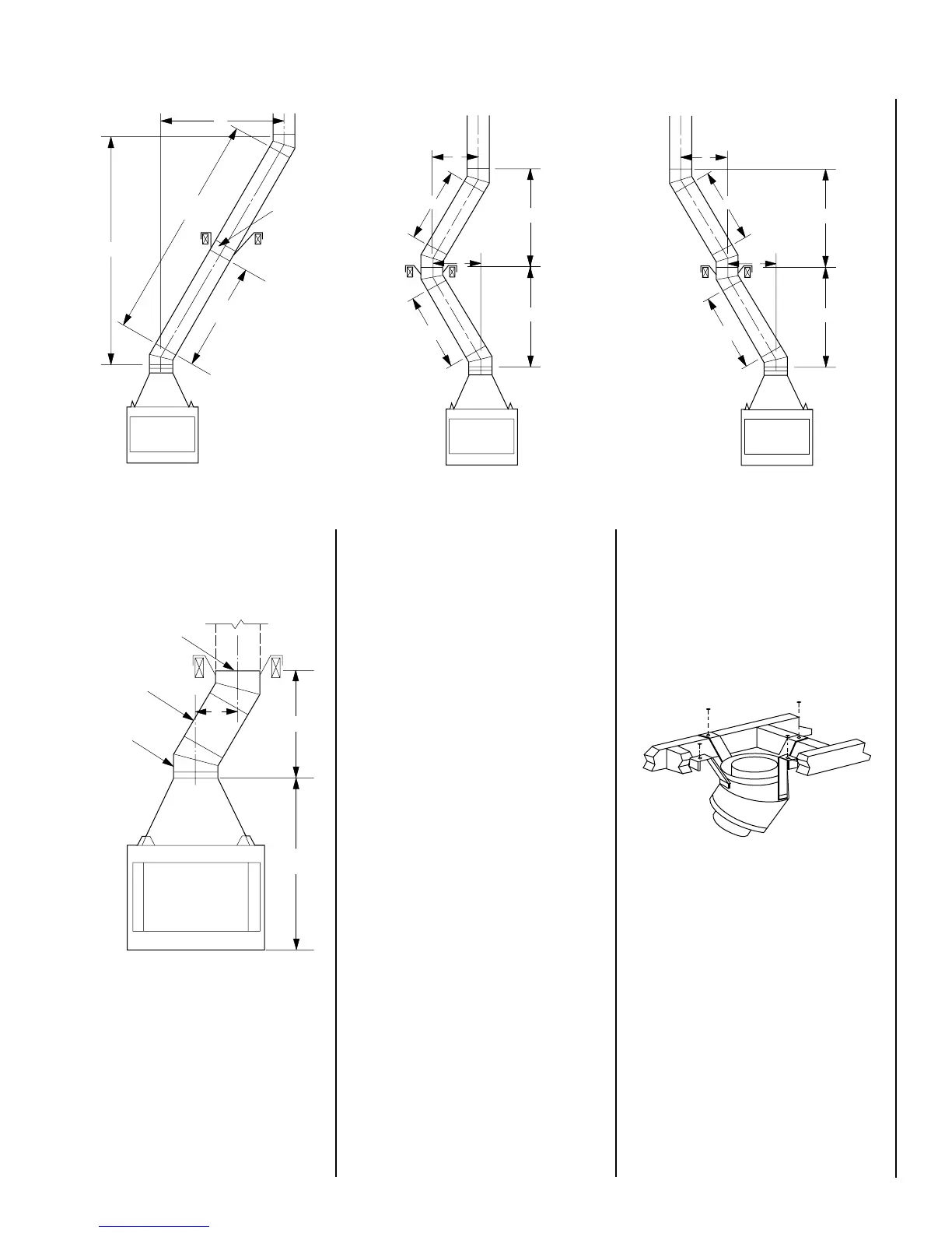
TO INSTALL OFFSETS
First, review Offset Elevation Chart and
Figure
40
for reference.
Figure 40
Step 1. Determine the offset distance where
chimney is to pass through the first ceiling-
dimension “A.” To find this point on your
ceiling, first determine the center point for a
vertical chimney following the instructions for
vertical installation.
Measure height to the ceiling from the top of
fireplace-dimension “B.” Use Offset Elevation
Chart to find dimension “A.” Mark point where
you will drive your nail to show the center point
for your offset ceiling cut.
Step 2. Proceed by using the Straight Up Instal-
lation Instructions for cutting and framing ceil-
ing and roof openings.
Note: See Framing and Dimension Chart for the
sizes of the ceiling and roof openings. The size
of the roof opening varies with the degree of
pitch of the roof.
OFFSET ELBOW ASSEMBLY
Offset elbows install the same as chimney
sections. First, snap the inner section INTO the
preceding inner section of flue. Check connec-
tion by pulling up slightly to ensure a tight fit.
Next, the outer sections snap lock OVER the
preceding outer section of chimney. Again,
check outer section by pulling up slightly to
ensure proper connection is made.
RETURN ELBOW ASSEMBLY
Return elbows install the same way as round
terminations and stabilizers:
Step 1. Hold return elbow over top of last
chimney section.
Step 2. Center inner slip section into inner flue
pipe-slip down.
Figure 39 Figure 41
Figure 42
A
1
C
1
B
1
B
2
C
2
A
2
A
1
C
1
B
1
B
2
C
2
A
2
Stabilizer
A
1
20' Max.
(6m)
B
1
10' Max.
(3m)
TF10-E30*
Return Elbow
TF10 Chimney
Section (s)
TF10-30*
Offset Elbow
A
B
65 ¹⁄₄"
(1657mm)
* Part of Offset/Return Package, Model TF10-ES30
Return Elbow
13