2-1
Chapter 2: Jumpers and Pin Denitions
1
1
1
1
1
6
25
26
50
100
A1
A2
B1
B2
C1
C2
D1
D2
CG1
B7
B8
C8
A7
C7
D7
D8
A8
PRESS FIT
CG2CG3
A1
A2
B1
B2
C1
C2
D1
D2
CG1
B7
B8
C8
A7
C7
D7
D8
A8
PRESS FIT
CG2
CG3
3
2
1
4
BAR CODE
DESIGNED IN USA
BPN-SAS3-826A
REV:1.11
1
3
1 41
4
1
4
1
4
+
+
+
+
+
+
+
+
+
+
+
+
+ +
+
123
321
UB12
JP13
JP12
JP11
JP10
J27
JSM1
JSM2
Q6
Q2
Q5
Q1
JP6
MH9
MH1MH2
MH3
MH4
MH7
MH8
JP1
JPW1
JPW2
JPW3
JPW4
C70
C125
C42
C41
C40C39
C36
C33
C34
C35
C100
C78
TP21
TP20
CPLD_RST
JTAG
+5V
GND+12V
+5V
GND
+12V
+5VGND
+5V
GND+12V
A1
A2
B1
B2
C1
C2
D1
D2
CG1
B7
B8
C8
A7
C7
D7
D8
A8
PRESS FIT
CG2CG3
JSM3
Chapter 2
Jumpers and Pin Denitions
This manual covers the BPN-SAS3-826A backplane.
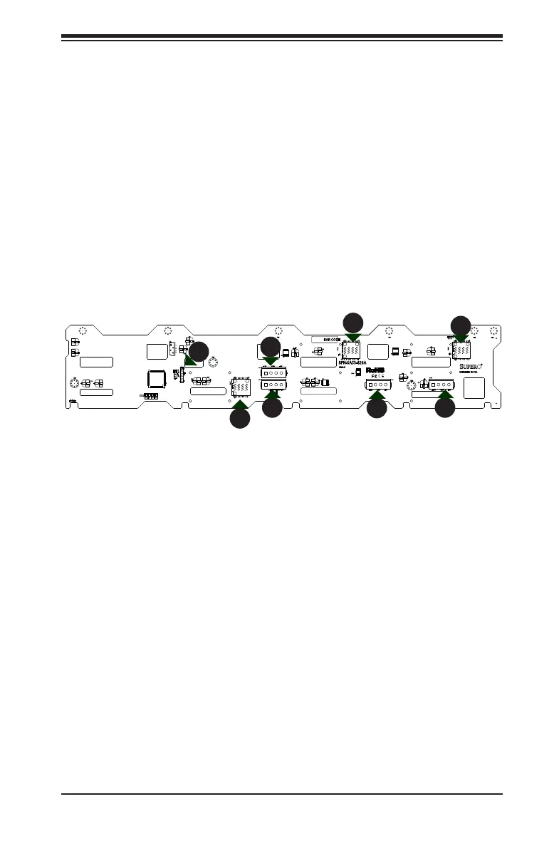
2-1 Rear Connector Locations
The following connectors are on the side of the backplane that faces the rear of the
chassis. They are marked by silkscreen labels.
1. Power Connectors, 4-pin: JPW1,
JPW2, JPW3 and JPW4.
2. JTAG Connector: JS27, CPLD
upgrade port (6-pin)
3. Mini SAS HD Connector: JSM1
4. Mini SAS HD Connector: JSM2
5. Mini SAS HD Connector: JSM3
1
1
1
1
1
1
1
1
1
5
4
1
3
Figure 2-1. Rear Connectors
1
2

 Loading...


