3-7
Chapter 3: Setup and Installation
3-3 Locating and Identifying Switches and Switch
Ports on a Blade Enclosure
Use this section to help you in locating and identifying the switch ports and switches on
a blade enclosure.
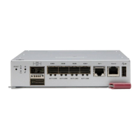
Locating and Identifying a Switch on a Blade Enclosure
When you are looking at the rear of the blade enclosure, you can identify the switch
associating with a CMM designation by using the information in Table 3-2.
Locating and Identifying a Switch Port on a Blade Enclosure
In general, a switch that is designated on the CMM as "Switch 1", has its ports
electrically routed to the first network interfaces of the blade servers, while the switch
designed as "Switch 2" has its ports electrically routed to the second network interfaces
of the blade servers. However, pass-through Ethernet modules have a one-to-one
relationship between their internal and external ports.
Managed switches have internal ports that are associated with the blade server slots
and network interfaces (NIC) as shown in Table 3-3.
Table 3-2. Locating and Identifying a Switch
Switch
Name
a
a. As shown on the CMM.
Switch Location
A1 Upper Left Slot
A2 Upper Right Slot
B1 Lower Left Slot
B2 Lower Right Slot
NOTE: Not all switches shown are supported on all blade enclosures. Please
check the Superblade matrix for the supported models.

 Loading...