11
Chapter 1: Introduction
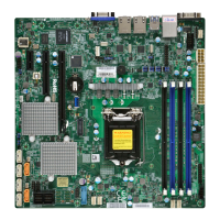
Notes:
• See Chapter 2 for detailed information on jumpers, I/O ports, and JF1 front panel con-
nections.
• " " indicates the location of Pin 1.
• Jumpers/LED indicators not indicated are used for testing only.
• When LEDPWR (Onboard Power LED indicator) is on, system power is on. Unplug the
power cable before installing or removing any components.
Quick Reference
LAN2
LAN1
USB0/1
USB6/7
(3.0)
VGA
SP1
Intel PCH
CPU
BIOS
LICENSE
MAC CODE
BAR CODE
IPMI CODE
IPMI_LAN
COM1
BT1
COM2
USB2/3
USB8(3.0)
J23
USB4/5
USB9/10(3.0)
JTPM1
JPWR1
JOH1
JPI2C1
LEDPWR
JD1
JPWR2
FAN1
FAN2
FAN3
FAN4
FAN5
FAN6
JF1
I-SGPIO2
I-SGPIO1
JL1
I-SATA3
I-SATA2
JSD1
JSD2
JSXB1C
JSXB1B
JSXB2
JSXB1A
JI2C1
JI2C2
JWD1
JPL2
JPG1
JPB1
JPME2
JBR1
LE1
JUIDB1
JBT1
LEDEC1
LEDBMC
JPL1
I-SATA7
I-SATA6
I-SATA4
I-SATA5
SRW2
SRW3
SRW1
SRW4
BMC
X11SSW-F
REV:1.01
Designed in the USA
JIPMB1
JSTBY1
DIMMA1
DIMMA2
DIMMB1
DIMMB2
2260
2280
22110
JL1
VGA
LAN2
LAN1
USB8
USB0/1
COM1
IPMI_LAN
JUIDB1 LE1
COM2
SP1
USB4/5
USB9/10
JIPMB1
JSTBY1
USB6/7
JTPM1
JOH1
JPI2C1
LEDPWR
FAN1FAN2FAN3FAN4
JF1
I-SGPIO1
I-SGPIO2
I-SATA3
I-SATA2
JSD1
JSD2
JSXB1C
JSXB1B
JSXB1A
JSXB2
I-SATA7
I-SATA6
I-SATA4
I-SATA5
DIMMA1
DIMMA2
DIMMB1
DIMMB2
JBT1
LEDEC1
LEDBMC
BT1
JPL1
J23
JPB1
JI2C1
JI2C2
JPG1
JPL2
JBR1
JWD1
JPME2
FAN5FAN6
JPWR1
JPWR2
JD1
USB2/3

 Loading...