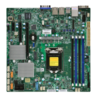
22
X11SSW-F User Manual
LAN2
LAN1
USB0/1
USB6/7
(3.0)
SP1
Intel PCH
CPU
BIOS
LICENSE
MAC CODE
BAR CODE
IPMI CODE
IPMI_LAN
BT1
COM2
USB2/3
USB8(3.0)
J23
USB4/5
USB9/10(3.0)
JTPM1
JPWR1
JOH1
JPI2C1
LEDPWR
JD1
JPWR2
FAN1
FAN2
FAN3
FAN4
FAN5
FAN6
JF1
I-SGPIO2
I-SGPIO1
JL1
I-SATA3
I-SATA2
JSD1
JSD2
JSXB1C
JSXB1B
JSXB2
JSXB1A
JI2C1
JI2C2
JWD1
JPL2
JPG1
JPB1
JPME2
JBR1
LE1
JUIDB1
JBT1
LEDEC1
LEDBMC
JPL1
I-SATA7
I-SATA6
I-SATA4
I-SATA5
SRW2
SRW3
SRW1
SRW4
BMC
X11SSW-F
REV:1.01
Designed in the USA
JIPMB1
JSTBY1
DIMMA1
DIMMA2
DIMMB1
DIMMB2
2260
2280
22110
2.2 Motherboard Installation
All motherboards have standard mounting holes to t different types of chassis. Make sure
that the locations of all the mounting holes for both the motherboard and the chassis match.
Although a chassis may have both plastic and metal mounting fasteners, metal ones are
highly recommended because they ground the motherboard to the chassis. Make sure that
the metal standoffs click in or are screwed in tightly.
Location of Mounting Holes
Note: 1) To avoid damaging the motherboard and its components, please do not use
a force greater than 8 lb/inch on each mounting screw during motherboard installation.
2) Some components are very close to the mounting holes. Please take precautionary
measures to avoid damaging these components when installing the motherboard to
the chassis.
Philips
Screwdriver
(1)
Standoffs (7)
Only if Needed
Philips Screws
(7)
Tools Needed

 Loading...