44
X11SSW-F User Manual
Required Connection
+12V 8-pin Power
Pin Denitions
Pin# Denition
1 - 4 Ground
5 - 8 +12V
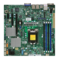
Secondary Power Connector
JPWR2 must also be connected to the power supply. This connector is used to power the
processor(s).
1. 8-Pin PWR (Required)
1
LAN2
LAN1
USB0/1
USB6/7
(3.0)
VGA
SP1
Intel PCH
CPU
BIOS
LICENSE
MAC CODE
BAR CODE
IPMI CODE
IPMI_LAN
COM1
BT1
COM2
USB2/3
USB8(3.0)
J23
USB4/5
USB9/10(3.0)
JTPM1
JPWR1
JOH1
JPI2C1
LEDPWR
JD1
JPWR2
FAN1
FAN2
FAN3
FAN4
FAN5
FAN6
JF1
I-SGPIO2
I-SGPIO1
JL1
I-SATA3
I-SATA2
JSD1
JSD2
JSXB1C
JSXB1B
JSXB2
JSXB1A
JI2C1
JI2C2
JWD1
JPL2
JPG1
JPB1
JPME2
JBR1
LE1
JUIDB1
JBT1
LEDEC1
LEDBMC
JPL1
I-SATA7
I-SATA6
I-SATA4
I-SATA5
SRW2
SRW3
SRW1
SRW4
BMC
X11SSW-F
REV:1.01
Designed in the USA
JIPMB1
JSTBY1
DIMMA1
DIMMA2
DIMMB1
DIMMB2
2260
2280
22110
Important: To provide adequate power supply to the motherboard, be sure to connect
the 24-pin ATX PWR and the 8-pin PWR connectors to the power supply. Failure to
do so may void the manufacturer warranty on your power supply and motherboard.

 Loading...