46
X11SSW-F User Manual
LAN2
LAN1
USB0/1
USB6/7
(3.0)
VGA
SP1
Intel PCH
CPU
BIOS
LICENSE
MAC CODE
BAR CODE
IPMI CODE
IPMI_LAN
COM1
BT1
COM2
USB2/3
USB8(3.0)
J23
USB4/5
USB9/10(3.0)
JTPM1
JPWR1
JOH1
JPI2C1
LEDPWR
JD1
JPWR2
FAN1
FAN2
FAN3
FAN4
FAN5
FAN6
JF1
I-SGPIO2
I-SGPIO1
JL1
I-SATA3
I-SATA2
JSD1
JSD2
JSXB1C
JSXB1B
JSXB2
JSXB1A
JI2C1
JI2C2
JWD1
JPL2
JPG1
JPB1
JPME2
JBR1
LE1
JUIDB1
JBT1
LEDEC1
LEDBMC
JPL1
I-SATA7
I-SATA6
I-SATA4
I-SATA5
SRW2
SRW3
SRW1
SRW4
BMC
X11SSW-F
REV:1.01
Designed in the USA
JIPMB1
JSTBY1
DIMMA1
DIMMA2
DIMMB1
DIMMB2
2260
2280
22110
1
2
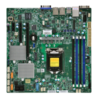
1. Chassis Intrusion
2. Internal Buzzer
Chassis Intrusion
A Chassis Intrusion header is located at JL1 on the motherboard. Attach the appropriate cable
from the chassis to inform you of a chassis intrusion when the chassis is opened. Refer to
the table below for pin denitions.
Chassis Intrusion
Pin Denitions
Pin# Denition
1 Intrusion Input
2 Ground
Internal Speaker/Buzzer
The Internal Speaker (SP1) can be used to provide audible notications using various beep
codes. Refer to the table below for pin denitions. Refer to the layout below for the location
of the internal buzzer.
Internal Buzzer
Pin Denitions
Pin# Denition
1 Pos (+) DC 5V
2 Neg (-) Signal In

 Loading...