46
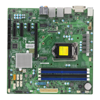
Super X13SCW-F User's Manual
3
+
X13SCW-F
REV:1.01
DESIGNED IN USA
BAR CODE
MAC CODE
IPMI CODE
BIOS LICENSE
JSXB1A JSXB1C
JSXB1B
JWD1
JPME2
JPL2
JPL1
JVRM1
JPG1
MH3
MH1
MH2
MH5
MH6
MH7
MH4
LEDPWR
LEDMCU1
LEDMCU2
LEDM1
JUIDB1
JTPM1
SRW4
SRW6
SRW7
SRW5
JPW2
JPFR2
JDBG5
JL1
FAN2
FAN6
FAN5
FAN3
FAN4
FAN1
JF1
JPI2C1
JPW1
JSATA1
JSXB2
JBT1
JNVME1
BT1
JSEN1
JIPMB1
J7
JDBG2
JBPNI2C1
(3.2(10 Gb))
USB8
(3.2(10 Gb))
CPU
SXB2:PCIe x4
SXB1B:PCIe x16
I-SATA0–7
M.2-P
M.2-C
M.2 NVME
M.2 NVME
1-2:ENABLE
JPG1:VGA
2-3:DISABLE
USB2/3
USB4/5
USB9/10(3.2)
COM2
PWR I2C
COM1
:TPM/PORT80
22110
2280
JBT1:CMOS CLEAR
IPMI_LAN
USB0/1
22110
2280
1-2:ENABLE
JPL1:LAN1
2-3:DISABLE
USB6/7
1-2:RST
JWD1:Watch Dog
2-3:NMI
JPME2
1-2:Normal
2-3:ME MANUFACTURING MODE
DIMMA1
VGA
JF1
RST
ON
PWR
OH
FAIL
FF
PWR
2
NIC
NIC
PWR
HDD
LED
1
NMI
X
DIMMA2
DIMMB1
DIMMB2
LAN1LAN2
UID-LED
UID-SW
1-2:ENABLE
JPL2:LAN2
2-3:DISABLE
JL1:CHASSIS INTRUSION
LE6
C266
BMC
JTPM1
Headers
1. JIPMB1
2. JBPNI
2
C1
3. Chassis Intrusion
4-pin BMC External I
2
C Header
A System Management Bus header for IPMI 2.0 is located at JIPMB1. Connect the appropriate
cable here to use the IPMB I
2
C connection on your system. Refer to the table below for pin
denitions. JBPNI2C1 is used to updated the CPLD of the BPN-NVME5-LA15-S4 backplane.
Note: The cables for JIPMB1 and JBPNI2C1 must be equal to or shorter than 30 cm.
Chassis Intrusion
A Chassis Intrusion header is located at JL1 on the motherboard. Attach the appropriate cable
from the chassis to inform you of a chassis intrusion when the chassis is opened. Refer to
the table below for pin denitions.
Chassis Intrusion
Pin Denitions
Pin# Denition
1 Intrusion Input
2 GND
1
2
External I
2
C Header
Pin Denitions
Pin# Denition
1 Data
2 GND
3 Clock
4 NC
NC = No Connection
 Loading...


