Do you have a question about the Supermicro X13SCW-F and is the answer not in the manual?
Describes the target audience and purpose of the manual for the X13SCW-F motherboard.
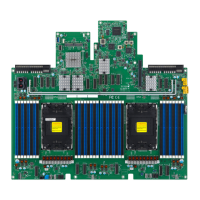
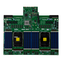
Provides a detailed overview of the Supermicro X13SCW-F motherboard's features and specifications.
Explains the symbols and conventions used throughout the manual for clarity and safety.
Provides contact information for Supermicro's main headquarters.
Provides contact information for Supermicro's European operations.
Provides contact information for Supermicro's Asia-Pacific operations.
Lists the main parts included with the Supermicro X13SCW-F motherboard shipment.
Provides essential links for drivers, utilities, FAQs, and support for the motherboard.
Provides important usage notes for jumpers, I/O ports, and front panel connections.
Lists and describes various motherboard connectors, including their default settings.
Details the supported CPU types and core counts for the motherboard.
Specifies the maximum memory capacity and speed supported by the motherboard.
Identifies the primary chipset used on the motherboard.
Lists the available expansion slots, including PCIe and M.2 types.
Details the integrated network controllers and their specifications.
Specifies the Baseboard Management Controller model.
Describes the graphics controller capabilities.
Lists and describes the various input/output devices and ports.
Details the motherboard's peripheral connectivity options, including USB ports.
Provides information about the BIOS chip and its supported features.
Outlines the power management features supported by the motherboard.
Describes features for monitoring system voltage, temperature, and fan status.
Explains the fan control mechanisms and supported headers.
Details system management features like TPM and watchdog.
Lists and describes the various LED indicators on the motherboard.
Specifies the physical dimensions of the motherboard.
Explains the BIOS setting for system behavior after an AC power loss.
Details the onboard voltage monitoring capabilities and alerts.
Describes fan status monitoring and control via IPMI.
Explains how system and CPU temperatures are monitored and managed.
Describes the system resource alert feature, often used with SuperDoctor 5.
Covers precautions and procedures for handling static-sensitive components.
Lists essential precautions to prevent ESD damage to components.
Provides guidelines for safely unpacking the motherboard to prevent static damage.
Lists the tools required for motherboard installation.
Describes how to locate and align motherboard mounting holes with chassis standoffs.
Provides step-by-step instructions for installing the LGA 1700 processor.
Details the motherboard's memory support, including type, speed, and population.
Illustrates and defines the rear I/O panel port layout and functions.
Describes the function and pin definitions of the Unit Identifier Switch.
Details the color and status of the Unit Identifier LED.
Diagram illustrating the pin assignments for the front control panel header (JF1).
Details the power supply connectors required for the motherboard.
Provides pin definitions for the 24-pin ATX power supply connector.
Describes the 4-pin BMC external I2C header for IPMI 2.0.
Explains the chassis intrusion header for detecting unauthorized access.
Explains the basic function and operation of motherboard jumpers.
Describes the procedure for clearing the CMOS settings and passwords.
Describes the BMC Heartbeat LED and its normal operational status.
Explains the BMC LAN LEDs indicating link status and activity.
Provides systematic procedures for diagnosing and resolving system issues.
Lists initial checks to perform before powering on the system.
Troubleshooting steps for when the system does not power on.
Step-by-step instructions for removing the onboard battery.
Provides guidelines for the safe and compliant disposal of used batteries.
Provides instructions for correctly installing an onboard battery.
Introduces the AMIBIOS Setup utility for motherboard configuration.
Explains how to enter the BIOS setup utility using hot keys.
Allows configuration of the system's date and time settings.
Displays BIOS version, build date, and MCU version information.
Displays the total amount of memory available in the system.
Manages boot-related display options like Quiet Boot and Option ROM Messages.
Controls whether POST messages or the OEM logo are displayed during boot.
Sets the display mode for Option ROM messages during system startup.
Enables the Watch Dog Timer for system resets based on inactivity.
Selects the performance state (Power Saving, Turbo) before OS handover.
Enables automatic adjustment of CPU voltage and frequency for power saving.
Dynamically increases CPU frequency to enter C-States faster for power reduction.
Enables CPPC v2 interface for controlling CPU P-States.
Enables or disables Per Core P State OC Control Mode for CPU performance.
Configures the Package Power Limit 1 in milliwatts or milli-percents.
Sets the duration for which Power Limit 1 may be exceeded.
Configures Package Power Limit 3 in milliwatts or milli-percents.
Sets the duration for which Power Limit 3 may be exceeded.
Sets the duty cycle for processor maintaining Power Limit 3.
Enables or disables changing Power Limit 3 configurations during OS.
Configures Package Power Limit 4 in milliwatts or milli-percents.
Enables or disables changing Power Limit 4 configurations during OS.
Enables enhanced C-States (C1E) for minimum CPU speed in C-State.
Prevents unnecessary excursion into C-States.
Enables or disables un-demotion of C-States.
Enables or disables Package C-State Demotion.
Enables or disables Package C-State Un-Demotion.
Enables or disables C-State Pre-Wake functionality.
Provides configuration options for the System Agent.
Displays and allows configuration of memory-related parameters.
Sets the LFSR mask for Row Hammer pTRR feature.
Configuration for the M.2-C slot, including ASPM and PCIe Speed.
Sets the Active State Power Management level for PCIe devices.
Selects the PCI Express port speed.
Indicates presence and enables/disables the RSC-W-68G5 SLOT2 PCIe 5.0 x16 port.
Indicates presence and enables/disables the RSC-W-68G5 SLOT1 PCIe 5.0 x16 port.
Sets the number of stop-grant cycles for PCIe configurations.
Configuration options for PCI Express ports.
Sets ASPM level for PCIe device, specifically for ASPM 6.
Configures PCI Express L1 Substates.
Selects the PCI Express port speed.
Configuration for the M.2-P slot, including ASPM and PCIe Speed.
Enables/disables Serial Port 1 and configures its device settings.
Enables or disables the serial port and shows device settings.
Configures the IRQ setting for Serial Port 1.
Enables/disables Serial Port 2 and configures its device settings.
Enables or disables Serial Port 2 and shows device settings.
Sets the attribute for Serial Port 2 (SOL or COM).
Enables console redirection support for serial ports COM1, SOL, and COM2.
Specifies data exchange between host and remote computers for console redirection.
Selects the target terminal emulation type for console redirection.
Sets the transmission speed for serial ports used in console redirection.
Sets the data transmission size for console redirection.
Configures parity bit settings for serial data transmission.
Enables COM port EMS Console Redirection.
Selects serial port for Windows Emergency Management Services (EMS).
Selects terminal emulation type for EMS console redirection.
Sets transmission speed for EMS serial ports in console redirection.
Enables or disables SATA device connectivity.
Selects the SATA mode (AHCI or Intel VROC SATA RAID).
Selects the interrupt for operating system availability.
Enables aggressive link power state management for the PCH.
Designates specified SATA ports for hot plugging.
Activates the High Precision Event Timer (HPET) for precise timing.
Grants control of PCIe Native hot plug and power management.
Workaround for OS without XHCI hand-off support.
Enables USB mass storage driver support.
Common settings for PCI devices, including SR-IOV and DMA Mitigation.
Enables or disables Single Root IO Virtualization Support.
Helps block DMA attacks by enabling this feature.
Selects the Onboard Video Option ROM type.
Enables remapping of BIOS above 4GB.
Selects EFI to boot with installed PCIe devices.
Enables or disables onboard LAN ports.
Sets PCIe Clock to Native or FREE_RUNNING.
Enables Unified Extensible Firmware Interface (UEFI) for network stack.
Enables IPv4 Preboot Execution Environment (PXE) for boot support.
Indicates if network address configuration was successful.
Sets the DHCP configuration for network address assignment.
Enters the local IP address for the computer.
Enters the subnet mask for the computer.
Enters the gateway IP address for the computer.
Enters the DNS server addresses for the computer.
Accesses the IPv6 network configuration menu.
Enters an ID for the network device.
Sets the count for Duplicate Address Detection (DAD).
Sets the network policy to Automatic or Manual.
Advanced IPv6 network settings configuration.
Enters a new IPv6 address.
Enters a new gateway IP address.
Enters a new DNS server address.
Enables BIOS support for onboard security devices.
Enables SHA256 PCR Bank support for system integrity.
Schedules a TPM-related operation for system data integrity.
Selects the policy for HTTP Boot (all LANs, each LAN, or priority).
Enables/disables HTTPS boot hostname check for TLS certificates.
Ranks the targeted port for HTTP boot priority.
Sets the priority for HTTP boot instance 1.
Enters the KMS server IPv4 address.
Enters the second KMS server IPv4 address.
Sets the Supermicro KMS TCP port number.
Sets the KMS server connection time-out in seconds.
Enters the correct time zone for the system.
Sets the client identity (user name) for KMS.
Sets the client identity (password) for KMS.
Manages CA certificates for KMS TLS.
Manages client certificates for KMS TLS.
Manages client private keys for KMS TLS.
Changes the private key password.
Enables Super-Guardians protection for Storage, System, or both.
Manages server CA certificates for TLS authentication.
Enrolls certification from a specified file.
Inputs the certification Global Unique Identifier (GUID).
Enrolls client certificates.
Enrolls client certification from a file.
Inputs the certification Global Unique Identifier (GUID).
Specifies the port speed for the network port.
Enables or disables Wake On Lan support.
Identifies the physical network port by blinking its associated LED.
Configures SMBIOS Event Log settings, including enabling/disabling.
Enables or disables SMBIOS Event Logging during system boot.
Configures how and when the SMBIOS event log is erased.
Sets the conditions for erasing event log data.
Determines action when the event log memory is full.
Toggles system boot event logging to enabled or disabled.
Counts occurrences of duplicate events before MECI counter increments.
Defines time window between duplicate log events for MECI increment.
Indicates the BMC firmware revision number.
Shows the current status of the BMC firmware.
Manages system event logging within the BMC.
Enables or disables all system event logging at boot up.
Configures how and when System Event Logs (SEL) are erased.
Sets the conditions for erasing SEL logs upon system reboot.
Applies IP/MAC address changes at the next system boot.
Configures IPv4 network settings for the BMC.
Displays the BMC LAN setting (e.g., Failover).
Displays the BMC Network Link status.
Selects the source for the IP address (DHCP or Static).
Enters the VLAN ID for BMC network configuration.
Displays the status of the station IPv6 address to BMC.
Enables or disables IPv6 support for the BMC.
Sets or changes the administrator password for system security.
Sets or changes the user password when an administrator password is set.
Configures system password checks during BIOS setup and bootup.
Enables or disables freezing of Lock Security for storage drives.
Displays the name of the detected HDD.
Displays the serial number of the detected HDD.
Sets the security mode for storage device erase operations.
Shows the estimated time for security erase operations.
Indicates the status of the HDD user password.
Performs secure erase or sets passwords for storage devices.
Sets the user password for security functions.
Selects the secure boot mode (Standard or Custom).
Enables legacy device support when Secure Boot is enabled.
Restores manufacturer default keys for system security.
Resets the system to Setup Mode.
Enters Audit Mode workflow, erasing Platform Key variables.
Manages keys and signatures for secure boot.
Installs provision factory default settings in Setup Mode.
Enters and configures platform firmware keys.
Enters and configures Key Exchange Keys.
Enters and configures authorized signatures for the system.
Sets the time (seconds) to wait for the BIOS Setup activation key.
Selects the boot device type (Legacy, UEFI, Dual).
Enables booting from EFI OS if Legacy boot order fails.
Prioritizes the order of bootable devices.
Specifies the name for a new boot option.
Enters the path for the new boot option file.
Specifies the file path for the new boot option.
Creates the new boot option in the boot priority list.
Removes an EFI boot option from the boot order.
Options for saving changes or exiting the BIOS utility.
Exits BIOS without saving changes and reboots the computer.
Saves configuration changes and reboots the computer.
Saves configuration changes without rebooting the system.
Discards all changes and returns to the BIOS utility program.
Loads factory default settings for system stability.
Saves current BIOS settings as user defaults for future use.
Restores previously saved user-defined BIOS settings.
Selects a boot option to boot the system.
Lists common BIOS beep codes and their corresponding error messages.
Guides through installing the operating system, including RAID setup.
Steps for creating bootable media and initiating OS installation.
Provides warnings regarding battery replacement and handling.
Provides an overview of the Unified Extensible Firmware Interface (UEFI).
Explains the process of recovering the UEFI BIOS image.
| Form Factor | Micro-ATX |
|---|---|
| Chipset | Intel W680 |
| Memory Slots | 4 |
| Max Memory Capacity | 128 GB |
| IPMI | Yes |
| Socket Type | LGA 1700 |
| Video Output | DisplayPort |
| SATA Ports | 8 |
| Ethernet | 2 x 10GBase-T |