OWNERS MANUAL
14
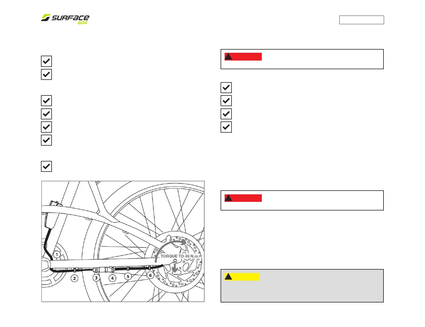
REMOVING AND INSTALLING BOLT-ON REAR WHEEL
TO INSTALL - Shift the rear derailleur to its outermost position
and pull the derailleur back with your right hand.
Put the chain on the smallest sprocket. Then, insert the wheel
into the frame dropouts and pull it all the way in to the dropouts.
The axle nut washers should be on the outside, between the
frame and the axle nut.
Make sure that the axle groove is pointing directly toward the
oor (6 o’clock).
Using the correct size wrench (15mm), tighten the axle nuts as
tightly as you can. Torque to 40 N.m. (30 ft/lbs)
Push the rear derailleur back into position.
Re-engage the brake quick release mechanism to restore correct
brake pad to disc clearance; spin the wheel to make sure it is cen-
ter in the frame and clears the brake pads; then squeeze the brake
lever and make sure that the brakes are operating correctly.
Reconnect the electric motor cables and fasten with zap- straps
in the required locations.
REMOVING AND INSTALLING BOLT-ON REAR WHEEL
TO REMOVE - Disconnect the electric motor cables and zap-
straps (located on the bottom left hand chain stay).
Shift the rear derailleur to high gear (the smallest rear sprocket)
and pull the derailleur body back with your right hand.
Using the correct size wrench, loosen the two axle nuts.
Lift the rear wheel o the ground a few inches and, with the
derailleur still pulled back, push the wheel forward and down
until it comes out of the rear dropouts.
WARNING:
!
The motor acts as a rear hub and should not
be adjusted once the rear wheel is properly mounted.
WARNING:
!
Riding with an improperly tightened seat post can
allow the seat to turn or move and cause you to lose control and fall.
SEATPOST QUICK RELEASE
The seat post quick release clamp works exactly like the front wheel
quick release. While a quick release looks like a long bolt with a lever
on one end and a nut on the other, the quick release uses a cam action
to rmly clamp the seat post.
The quick release cam squeezes the seat collar around the seat post to
hold the seat post securely in place. The tension- adjusting nut controls
the amount of clamping force. Turning the tension-adjusting nut clockwise
while keeping the cam lever from rotating increases the clamping force;
turning it counterclockwise while keeping the cam lever from rotating re-
duces clamping force. Less than half a turn of the tension-adjusting nut
can make the dierence between safe and unsafe clamping force.
CAUTION:
!
Your Surface604 bicycle is equipped with
disc brakes. Be very careful not to damage the disc, caliper or brake
pads when re-inserting the disc into the caliper. Never activate a disc
brakes control lever unless the disc is correctly inserted in the caliper.