1G-15 Fuel System:
Service Instructions
Fuel Pressure Relief Procedure
Z9J0111706001
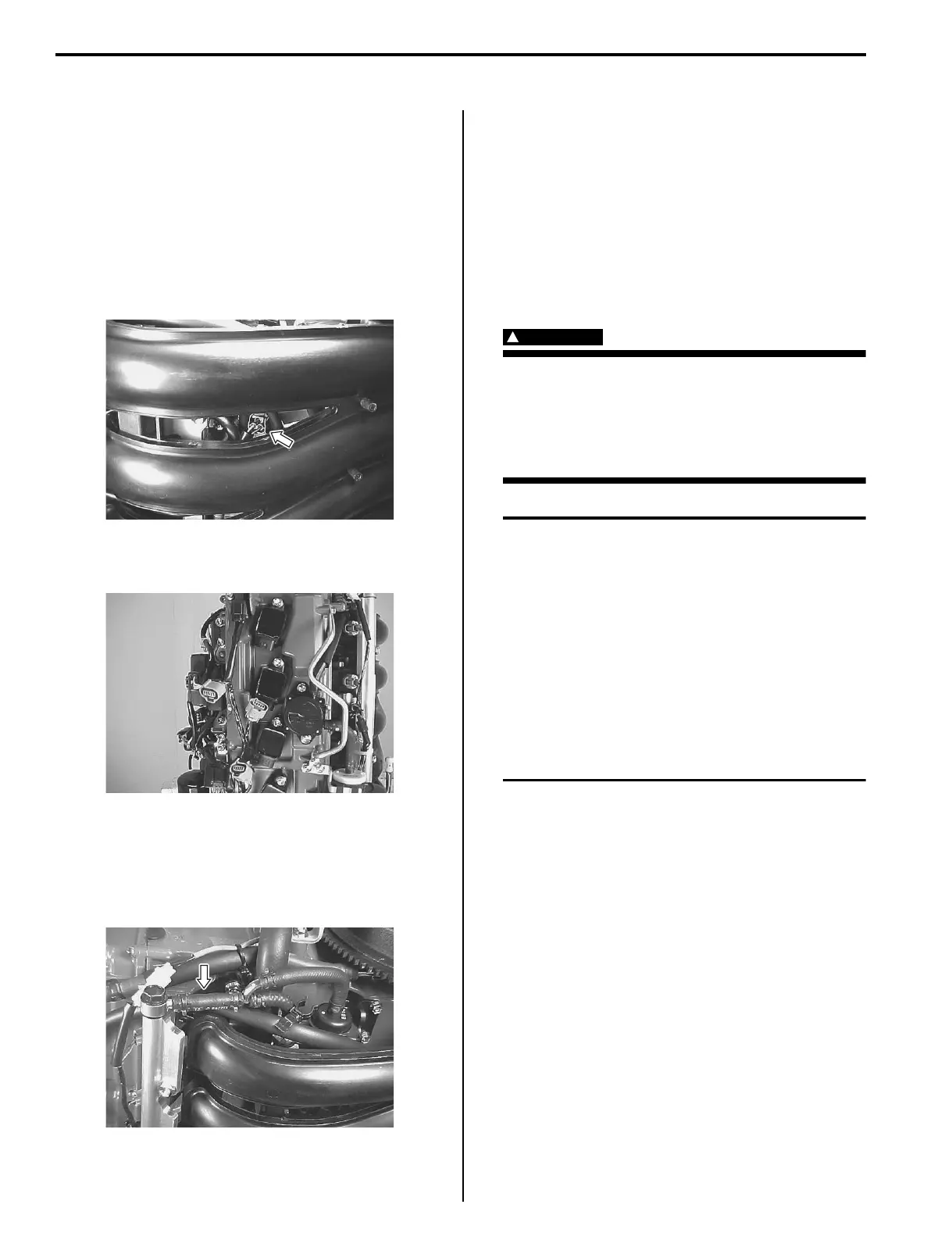
After making sure that engine is cold, relieve fuel
pressure as follows:
1) Turn “OFF” ignition switch.
2) Remove the ring gear cover.
Refer to “Ring Gear Cover Removal and Installation”
in Section 1D (Page 1D-2).
3) Disconnect the high pressure fuel pump lead wire
connector at high pressure fuel pump.
4) Disconnect the ignition coil primary lead wire
connectors from all of the ignition coils.
5) Crank the engine 5 – 10 times (3 seconds each time)
to dissipate the fuel pressure in lines.
6) Make sure fuel pressure has been relieved by
pinching the high pressure fuel hose between finger
tips (the line should feel soft, without pressure).
7) Upon completion of servicing, connect the ignition
coil primary lead wire and the high pressure fuel
pump lead wire.
8) Install the ring gear cover.
Refer to “Ring Gear Cover Removal and Installation”
in Section 1D (Page 1D-2).
Fuel Line Removal and Installation
Z9J0111706002
Pay special attention to the following points when
removing or installing fuel hoses.
WARNING
!
Fuel components and fuel hoses after the
high pressure fuel pump remain pressurized
at all times.
To protect against fuel spray, relieve the fuel
line pressure before disconnecting or
removing components.
CAUTION
• Do not over bend (kink) or twist hoses
when installing.
• When installing hose clamps, position the
tabs to avoid contact with other parts.
• Be sure hoses do not contact rods, levers
or other components with engine either
operating or at rest.
• Extreme care should be taken not to cut,
abrade or cause any other damage to
hoses.
• Use care not to excessively compress
hoses when tightening the clamps.
• The fuel feed line is under high pressure, use special
care when servicing it.
• Spilled gasoline should be wiped off immediately.
• Perform the following checks to ensure proper and
safe operation of the repaired unit.
– Check fuel hose routing.
Refer to “Fuel Hose Routing” in Section 4B
(Page 4B-1).
– Check for fuel leakage.
Refer to “Fuel Leakage Check Procedure”
(Page 1G-16).
Fuel Line Inspection
Z9J0111706003
Visually inspect fuel lines for evidence of fuel leakage,
cracking, deterioration, or damage. Make sure all clamps
are secure. Replace parts as needed.
I9J011170028-01
I9J011170029-01
I9J011170030-01
 Loading...


