4-24 FI SYSTEM DIAGNOSIS
Step2
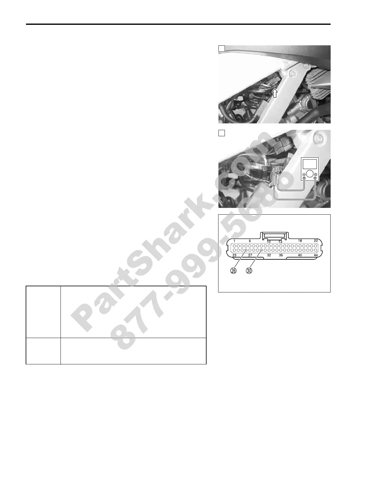
1) Disconnect the CKP sensor coupler.
2) Crank the engine a few seconds with the starter motor, and
measure the CKP sensor peak voltage at the coupler.
% CKP sensor peak voltage: 3.7 V and more
(
+ White –
- Green)
3) Repeat the above test procedure a few times and measure
the highest peak voltage.
If OK, then measure the CKP sensor peak voltage at the
ECM terminals. (
P –
T)
! 09900-25008: Multi circuit tester set
' Tester knob indication: voltage (()
Is the voltage OK?
2
2
V
YES
• B/W or White wire open or shorted to ground, or
poor
P or
T connection.
• If wire and connection are OK, intermittent trou-
ble or faulty ECM.
• Recheck each terminal and wire harness for
open circuit and poor connection.
NO
• Loose or poor contacts on the CKP sensor cou-
pler or ECM coupler.
• Replace the CKP sensor with a new one.
PartShark.com
877-999-5686
 Loading...


