8-22 ELECTRICAL SYSTEM
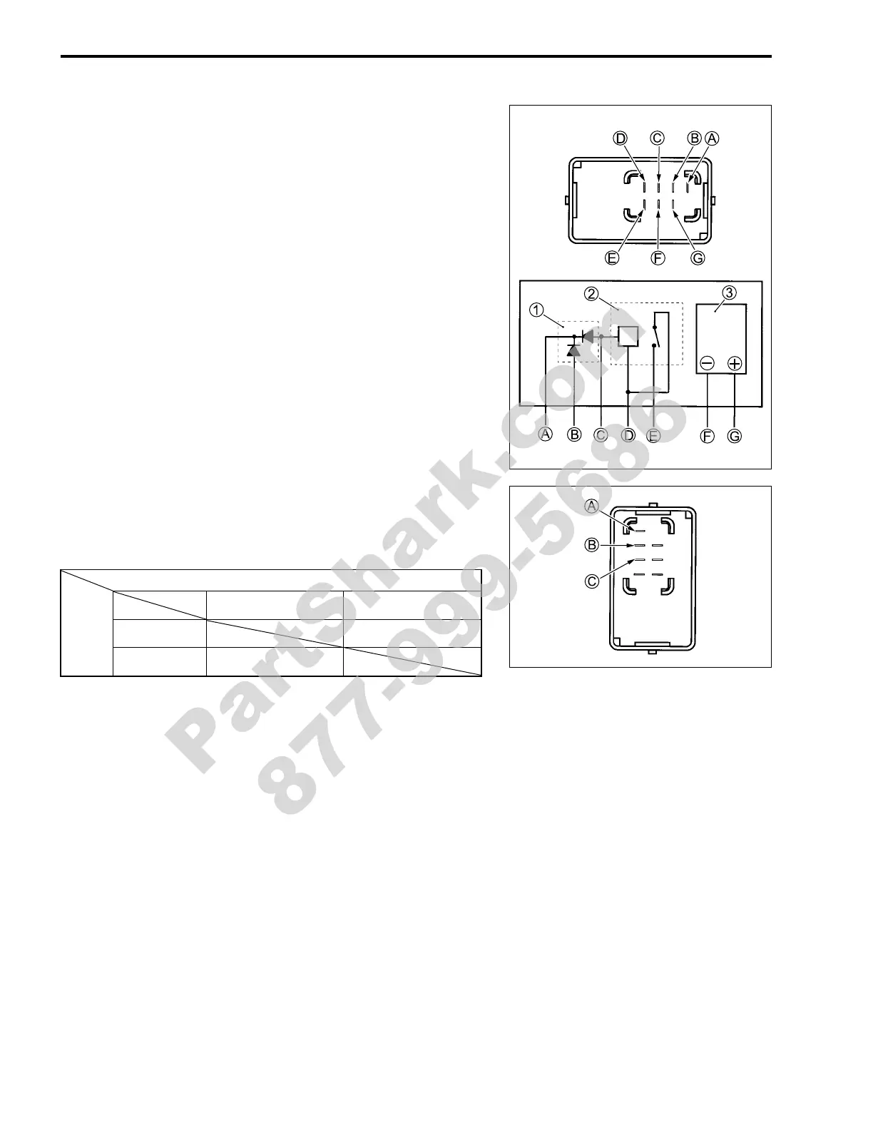
SIDE-STAND RELAY INSPECTION
First check the insulation between
D and
E terminals with the
tester. Then apply 12 V to terminals
D and
C (
+ to
D and
- to
C) and check the continuity between
D and
E. If there is no
continuity, replace the turn signal/side-stand relay with a new
one.
# 09900-25008: Multi circuit tester set
+ Tester knob indication: Continuity test (,)
1 Diode
2 Side-stand relay
3 Turn signal relay
DIODE INSPECTION
Measure the voltage between the terminals using the multi cir-
cuit tester. Refer to the following table.
Unit: V
# 09900-25008: Multi circuit tester set
) Tester knob indication: Diode test (*)
NOTE:
If the multi circuit tester reads 1.4 V and below when the tester
probes are not connected, replace its battery.
+ Probe of tester to:
- Probe of
tester to:
C,
B
A
C,
B 1.4 V and more
A 0.4 – 0.6
PartShark.com
877-999-5686
 Loading...


