Do you have a question about the Suzuki VL1500 and is the answer not in the manual?
Lists the main sections of the service manual for quick navigation.
Explains warning, caution, and note symbols used in the manual.
Essential safety precautions for mechanics and operators.
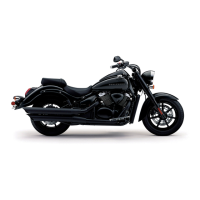
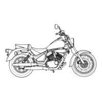
Visuals of the motorcycle's right and left sides.
Shows location of frame and engine serial numbers.
Recommended fuel types, octane, and engine oil specifications.
Specifies SUZUKI PERFORMANCE 4 MOTOR oil and viscosity.
Recommends SAE 90 hypoid gear oil for the final drive.
Advises using DOT 4 brake fluid and warns against mixing types.
Specifies SUZUKI FORK OIL SS-08 (#10) for front forks.
Outlines procedures for breaking in new motorcycle parts.
Identifies engine cylinders as #1 and #2 from rider's view.
Illustrates and lists various information labels on the motorcycle.
Detailed specs for dimensions, mass, engine, transmission, electrical.
Lists codes associated with countries and areas.
Details recommended maintenance intervals and service requirements.
Chart of maintenance tasks and intervals for components.
Illustrates and indicates major lubrication points on the motorcycle.
Describes servicing procedures for maintenance chart items.
Inspecting and replacing spark plugs, including heat range.
How to check and clean carbon deposits on spark plugs.
Specifies correct spark plug gap measurement and procedure.
Guidance on inspecting spark plug electrode condition for replacement.
Installing spark plugs and plug caps, including torque.
Inspecting and cleaning the air cleaner element.
When to replace engine oil and oil filter, and procedures.
Inspecting fuel hoses for damage or leakage.
Inspecting and replacing the fuel strainer.
Procedure for adjusting engine idle speed.
Inspecting and adjusting the automatic de-compression cable.
Checking and adjusting throttle cable play.
Steps for synchronizing carburetors.
Maintenance for the evaporative emission control system.
Maintenance for the PAIR (air supply) system.
Procedures for inspecting and maintaining the clutch.
Maintenance procedures for front and rear brakes.
How to check and maintain brake fluid level.
Instructions on checking brake pad wear.
Detailed steps for bleeding air from the brake fluid circuit.
How to adjust brake pedal height.
How to adjust brake light switch.
Procedures for replacing and checking final gear oil.
Guidance on tire inspection and tread condition.
How to inspect tire condition and tread depth.
Recommended tire pressure for solo and dual riding.
How to inspect and adjust steering.
Instructions for inspecting front forks for oil leakage or damage.
Instructions for inspecting rear suspension.
Torque specifications for exhaust pipe and muffler bolts.
Torque specs for various chassis bolts and nuts.
Procedures and specs for checking engine compression pressure.
Procedures for checking engine oil pressure.
Lists engine parts removable without engine removal.
Step-by-step instructions for engine removal and installation.
Procedures for engine disassembly and reassembly.
Removal, servicing, and installation of camshafts, cylinder heads, and covers.
Cylinder and piston removal, servicing, and installation procedures.
Procedures for clutch removal, inspection, installation, and related parts.
Information on starter system, generator, and signal generator.
Procedures for gearshift linkage removal, inspection, and installation.
Exploded views and procedures for crankcase, transmission, crankshaft, conrod.
Procedures for removing transmission, crankshaft, and conrod.
Diagrams and details of the engine lubrication system.
Exploded view and components of the shaft drive system.
Detailed illustration of secondary bevel gear components.
Steps for removing the secondary bevel gear.
Procedures for disassembling the secondary bevel gear.
Guidelines for inspecting secondary bevel gears for damage or wear.
Instructions for measuring damper spring free length.
Procedures for adjusting secondary gear shims for backlash.
Detailed illustration of final bevel gear assembly.
Explains function and routing of final gear case breather circuit.
Steps for removing the final gear case.
Procedures for disassembling the final gear case.
Guidelines for inspecting final gear case components.
How to measure and adjust backlash in final gear assembly.
Procedures for checking and adjusting tooth contact.
Steps for reassembling the final gear case.
Procedures for installing the final gear case.
Overview of fuel system components and function.
Steps for removing the fuel tank.
Instructions for inspecting and removing the fuel pump.
Procedures for inspecting and installing the fuel strainer.
Procedures for removing and installing the fuel level gauge.
Details on removing fuel-vapor separator and shut-off valve.
Procedures for inspecting and installing the fuel tank inlet valve.
Information on TPC valve removal and installation.
Detailed diagram of carburetor components.
Carburetor specifications for different models.
Shows the location of the I.D. number on the carburetor.
Explains carburetor diaphragm and piston valve operation.
Description of the motorcycle's slow fuel system.
Explanation of transient enrichment system function.
Description of the main fuel system operation.
Explanation of the starter (enricher) system.
Description of the float system and its operation.
Steps to remove carburetor components.
Procedures for disassembling the carburetor.
Instructions for cleaning carburetor jets and circuits.
Guidance on inspecting carburetor components for damage or clogging.
Procedures for reassembling and remounting carburetor.
How to measure and adjust carburetor float height.
Procedures for inspecting throttle position sensor.
Steps for reassembling and remounting the carburetor.
Instructions for setting throttle valve position.
Instructions for installing and checking coasting valve.
Instructions for installing the funnel.
Procedures for reinstalling and adjusting pilot screw.
Instructions for applying grease to starter plunger O-ring.
Instructions for installing carburetor top cap and O-ring.
Procedures for engaging carburetors and applying grease.
How to position throttle position sensor.
Illustrates carburetor clamp positions.
Exploded view and detailed illustration of exterior parts.
Steps for removing the seat.
Steps for removing the rear seat.
Steps for removing frame covers.
Procedures for removing frame head and upper covers.
Steps for removing meter and fuel inlet cover.
Procedures for removing the rear fender.
Exploded view of front brake components.
Steps for replacing brake pads.
Procedures for replacing brake fluid and bleeding system.
Steps for removing and disassembling brake caliper.
Inspection of brake caliper and pistons.
Procedures for reassembling and remounting brake caliper.
Inspection of brake disc for cracks or damage.
Detailed illustration of front wheel assembly.
Procedures for installing the front wheel.
Detailed illustration of front fork components.
Steps for removing and disassembling front fork.
Inspection procedures for inner/outer fork tubes and springs.
Procedures for reassembling and remounting front fork.
Detailed illustration of steering system components.
Steps for removing and disassembling steering stem.
Inspection and disassembly of steering stem components.
Procedures for reassembling and remounting steering system.
Detailed illustration of rear wheel assembly.
Steps for removing the rear wheel.
Procedures for disassembling the rear wheel.
Inspection and disassembly of rear wheel components.
Instructions for inspecting wheel dampers.
Procedures for reassembling and remounting rear wheel.
Detailed illustration of rear suspension assembly.
Steps for removing rear suspension components.
Inspection and disassembly of swingarm and related parts.
Procedures for reassembling swingarm and shock absorber.
General cautions for servicing electrical components.
Precautions for connector handling and inspection.
Precautions for coupler handling and inspection.
Guidance on checking and replacing fuses.
Warning about handling semiconductor parts.
MF battery info, specs, and charging.
Step-by-step instructions for connecting battery terminals.
Guidance on proper wiring harness routing.
Instructions for using a multi-circuit tester.
Diagrams showing electrical component locations.
Description and function of charging system components.
Explains voltage regulator operation.
Troubleshooting guide for common electrical problems.
Procedures for inspecting battery current leakage.
How to inspect charging system output voltage.
How to inspect generator coil resistance.
How to inspect generator performance at no-load.
Procedures for inspecting regulator/rectifier.
Description of de-compression, starter, and interlock systems.
Description of side-stand/ignition interlock system.
Explains operation of side-stand/ignition interlock system.
Description of ignition system, including digital ignitor.
Details ignition system components and function.
Procedures for inspecting speedometer and meter.
Procedures for inspecting speed sensor.
How to inspect oil pressure indicator.
Information about various system relays.
Details on headlight and position light bulbs.
Information on headlight bulb types and replacement.
Specifications for various switches.
Battery specifications and initial charging.
Procedures for initial charging of a new battery.
Information on battery servicing.
Procedures for recharging the battery.
Troubleshooting for engine starting, noise, and running issues.
Troubleshooting for shaft drive noise and power transmission issues.
Troubleshooting for carburetor starting, idling, and fuel flow issues.
Troubleshooting for steering and wheel issues.
Troubleshooting for brake power, noise, and fluid issues.
Troubleshooting for electrical system issues like no spark, charging problems.
Troubleshooting for battery issues like sulfation and running down.
Wiring diagrams for various model variations.
Diagrams showing routing of wire harnesses, cables, and hoses.
Illustrates proper routing for fuel system hoses.
Shows correct routing for front brake hose.
Routing for rear brake hose on Y-models.
Illustrates proper routing for oil hoses.
Hose routing for PAIR (air supply) system.
Information on engine side box.
Procedures for setting up upper covers, meter, and fuel inlet cover.
Instructions for installing frame head and cover cushions.
Information about frame cover shield.
Procedures for setting up brake light and taillight.
Illustrations and part numbers of special tools for servicing.
Torque specifications for engine components.
Chart listing torque values for various bolt diameters.
Service data for valves, guides, camshafts, and cylinders.
Service data, specs, and procedures for VL1500XY models.
Detailed service data for valve, guide, camshaft, cylinder, piston.
Service data for front and rear brake calipers.
Inspection of fuel level gauge and resistance values.
Inspection procedures for speedometer and meter.
Wiring diagrams for various model variations.
Illustrates proper front brake hose routing.
Routing for rear brake hose on Y-models.
Diagram of evaporative emission control system for California models.
Hose routing for canister system.
| Displacement | 1462 cc |
|---|---|
| Bore x Stroke | 96.0 mm x 101.0 mm |
| Compression Ratio | 9.5:1 |
| Fuel System | Fuel injection |
| Ignition | Electronic ignition (transistorized) |
| Transmission | 5-speed constant mesh |
| Final Drive | Shaft drive |
| Front Suspension | Telescopic, coil spring, oil damped |
| Rear Brakes | Single hydraulic disc |
| Seat Height | 700 mm (27.6 in) |
| Engine Type | 4-stroke, liquid-cooled, SOHC, 54° V-twin |
| Rear Suspension | Link type, coil spring, oil damped |
| Fuel Tank Capacity | 18.0 L |
| Wheelbase | 1700 mm (66.9 in) |
| Front Brakes | Dual hydraulic disc |


