ELECTRICS
81
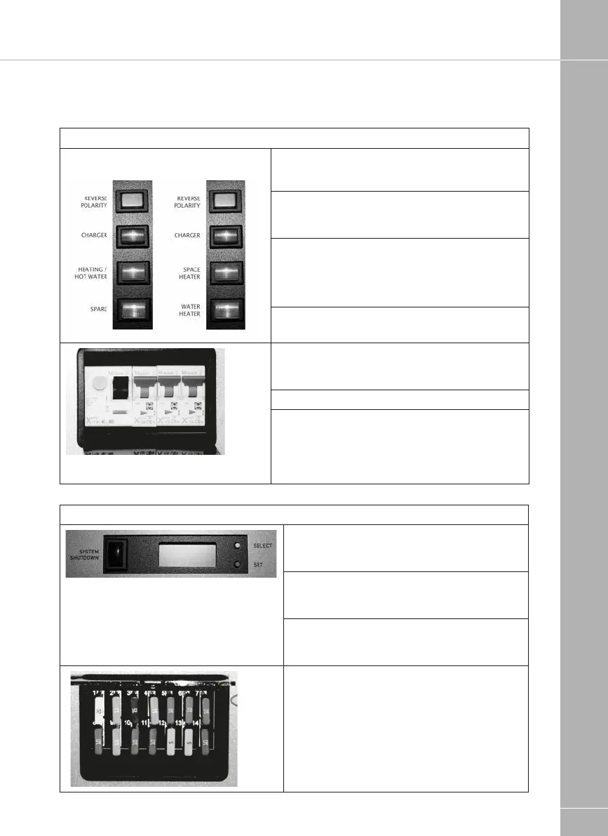
2.2 Power Supply Unit - Component Layout
230V Components
Red indicator – Reverse polarity indicator, lights up
when the 230V supply polarity is reversed.
Green push switch – Charger switch, this switch
turns the 12V battery charger on or off. “In” is on
“out” is off.
Amber push switch – Combi or Alde boiler, this
switch turns the 230V supply to the combination
heater / central heating system on or off. In is on
out is off.
White - Spare
Black lever switch, far left – Residual Current
protection Device (RCD) and main 230V on / off
switch.
Yellow button, far left – RCD test button.
Red lever switches, right – 3 x 10A Miniature
Circuit Breakers (MCB). Please note that installa-
tions with
a 3KW Alde heating system will have 2 x 10A and
1x16A MCB’s.
12V Components
Black push switch, far left – System shutdown
switch, this switch turns the power control
system on or off. In is on out is off.
Yellow push button, top right – Select button,
this button is used to scroll through the display
items on the LCD screen.
Red push button, bottom right – Set button,
this button is used to change the setting of the
displayed item on the LCD screen.
12V DC circuit protection fuses.
Fuse number 1 is top left;
Fuse number 14 is bottom, right.
See section 3.5 for full fuse allocation details.
Combi or
Alde installations
Space heater /Water
heater installations