1
LDR 02-22-2018 LA 9430
Specifi cations subject to change without notice.
Manufactured for: Swing-N-Slide® • 1212 Barberry Drive • Janesville, Wisconsin 53545 • USA • 1-800-888-1232 • www.swing-n-slide.com
Made in USA • Printed in USA
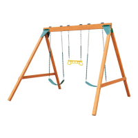
NE 4720, NE 4720-1T, NE 4720-1Y, NE 4720-3Y, NE 4720L, SP 2600, SP 2610, SP 2620, SP 2660,
SP 2670, SP 2680, SP 3029, SP 3079, SP 3088, SP 3099, SP 3100, SP 3200, SP 3300, SP 3500, WS 8200, WS 8201, WS 8202, WS 8336, WS 8337
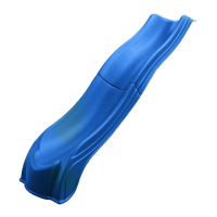
Slide Mounting Instructions
WARNING: ASSEMBLY BY ADULT.
Not Included In Kit:
Tools Required:
Assembly:
Fig. 2
Fig. 1
Fig. 3
Screw
Deck
Slide Block
Deck Screw
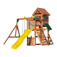
NE 3051, NE 3052, NE 3053, NE 3054, NE 3060, NE 3061, NE 3062, NE 4675-12PK, NE 4675-12T,
NE 4675-1PK, NE 4675-1T, NE 4675-3PK, NE 4675-3T, NE 4675L, NE 4675LY, WS 8334, WS 8335
Weight Limit: 250 lbs For children 2-10 years of age
Stake
2” x 4” x 17”
Use Pressure-Treated Wood
1-3/4”
17”
Cut
1-3/4”
(2) 1-1/4” screws
Pre-drill holes with 1/8” drill bit fi rst
Pre-drill dimple holes through slide with 1/4” drill bit fi rst
72”
USE ZONE
21”
21”
2” above ground
1-3/4”
Minimum
1-3/4” Minimum
Tape Measure
Hammer
1/8” & 1/4” Drill Bits
Phillips Bit
1-1/4” Truss Screws (not included)
(3 or 4 depending on model)
Stake
2” x 4” x 1 7”
Use Pressure-Treated Wood
Electric Drill
Circular Saw
x4
1-1/4”
(3,2 cm)
1/4”
(6 mm)
1/2”
(12,7 mm)
Truss Screw
Screw must be to sizes shown at a
minimum. Do not use a screw size shorter
than 1-1/4” (3,2 cm) long.
x2
1-1/4”
(3,2 cm)
Deck Screw
Screw size should be a #8 thread size
minimum and coated for use with
treated wood.
Fig. 4
Important: Slide could have three or four individual dimples or four sets of dimples. If it has a set of four dimples, use one screw at each set of dimples. Avoid locating dimples over any
gaps in the playset deck. Check for screws protruding underneath the deck. If screws protrude, add a wooden slide block underneath the deck to cover screw ends. See Fig. 4 for an
example slide block.
ASSEMBLY STEPS
1. Consult (Fig. 1) for proper placement of slide on your unit. Make certain no objects lie within the grayed out area, or ‘Use Zone.’ Position slide to determine proper location for stake.
IMPORTANT: Place the slide on level ground, not less than six feet from any structure or obstruction such as a fence, garage, house, overhanging branch, laundry line or electric wire.
Protective surfacing must extend a minimum of 6ft. in all directions from the perimeter of the equipment or from the outermost edges of any component. A slide extending beyond the
platform must have protective surfacing at least 6ft. out from both sides as well as the end. An area of 21” on either side of the slide should be free of obstructions which a child’s arm could contact.
2. Drive wood stake (not included) into ground leaving 2” exposed (Fig. 2).
3. Using an 1/8” drill bit, drill (2) holes through the side of the slide and into stake. Secure the slide bottom to the stake using (2) 1-1/4” deck screws (Fig. 2).
4. Attach slide to unit as shown in (Fig. 3).
x1
For 48” (121,9 cm) Deck Height
Instructions below apply to the following models:
For 60” (152,4 cm) Deck Height