Rev 2.0 Jan. 2024
2
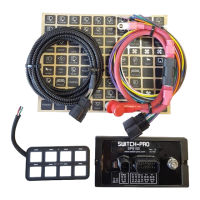
SP9100 SPECIFICATIONS
Power Module:
Size: 6.0” x 3.0” x 0.6”
Height with Connectors: 1.48”
Height with Connectors Plugged in and Wires: 2.8”
Enclosure Material: Anodized Aluminum
Temperature Rating: Automotive -40°C to 125°C
Water and Dust Proof Rating: IP67
Amperage Rating: 125A max
Switch 1 – 4 Outputs: 20A max
Switch 5 – 8 Outputs: 35A max
Current Draw: 35mA
Current Draw at Idle (1 min No Activity): 5.5mA
Current Draw in Sleep Mode (8 hrs No Activity): 3mA
Inputs Voltage Threshold - Active HIGH: > 4.5V
Inputs Voltage Threshold - Active LOW: < 0.5V
Switch Panel:
Size: 4.0” x 2.0” x 0.365”
Enclosure Material: Anodized Aluminum
Switch Panel Overlay and Legends Material:
Polycarbonate
Temperature Rating: -30°C to 85°C
Water and Dust Proof Rating: IP67
Backlighting Color: RGB
Switch LED Indicator Color: Amber
Bluetooth: BLE 4.1 Apple and Android
INSTALLATION
1. Switch Panel
1.1. Mounting Options
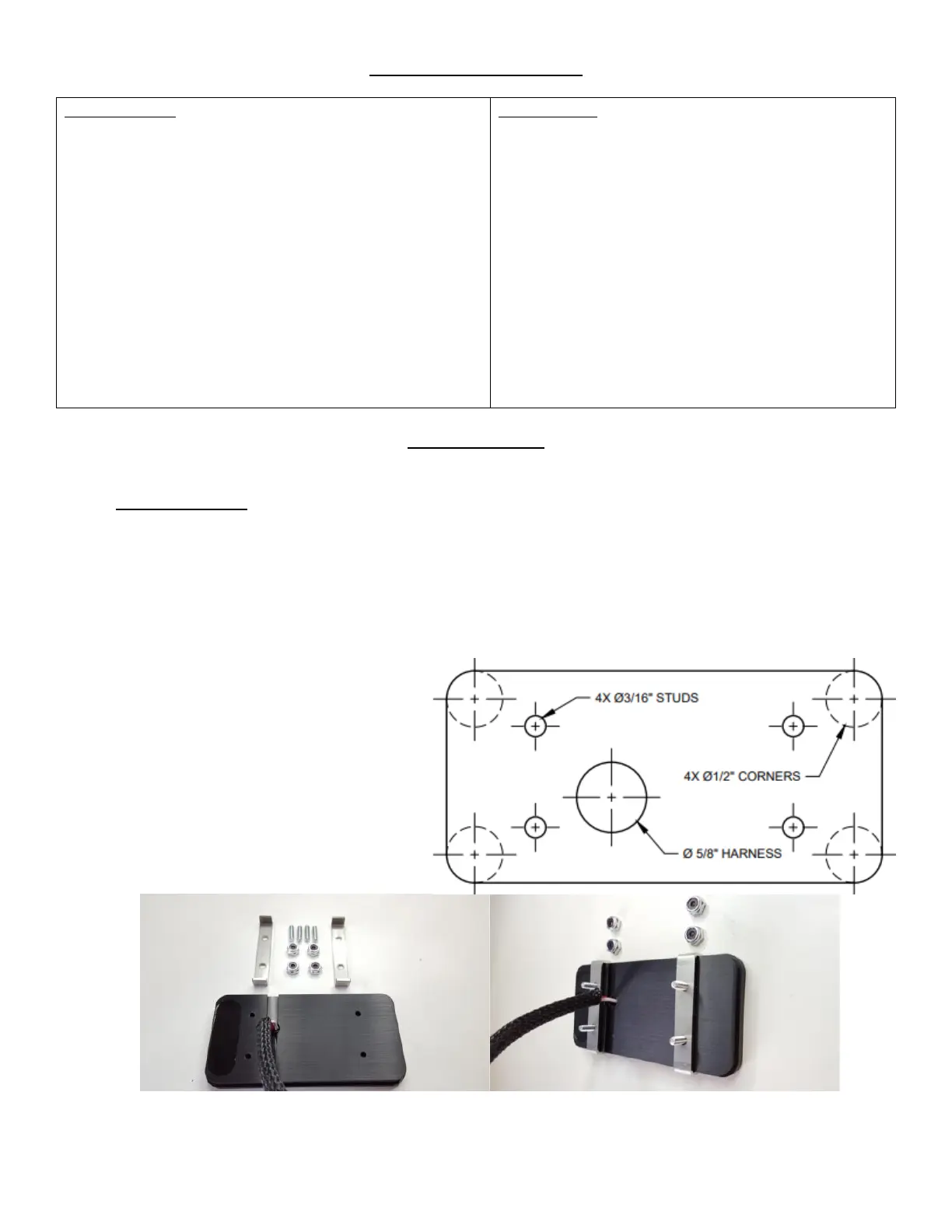
• Surface Mount: Drill four 3/16” holes for the 6-32 mounting studs and one 5/8 (0.625”) hole for the
harness and connector to feed through. Then, screw the threaded studs into the Switch Panel enclosure,
and secure the with the 6-32 nuts.
• Recessed Mount: Cut a rectangular opening measuring 3.885” x 1.885” with a corner radius of 0.25”.
Then, screw the four 6-32 threaded studs into the backside of the Switch Panel and tighten. Place the
Switch Panel into the opening and slide the two mounting brackets over the studs. Secure the mounting
brackets with the 6-32 nuts.
• Note: The diagram to the right can be
cut out and used as a template. The
diagram should measure
3.885” x 1.885” with a 0.25” corner
radius.
• Note: It is critical that the Switch
Panel be securely mounted to
eliminate strain on the wires on the
back, and to prevent rubbing against
anything that could damage the wires.
 Loading...