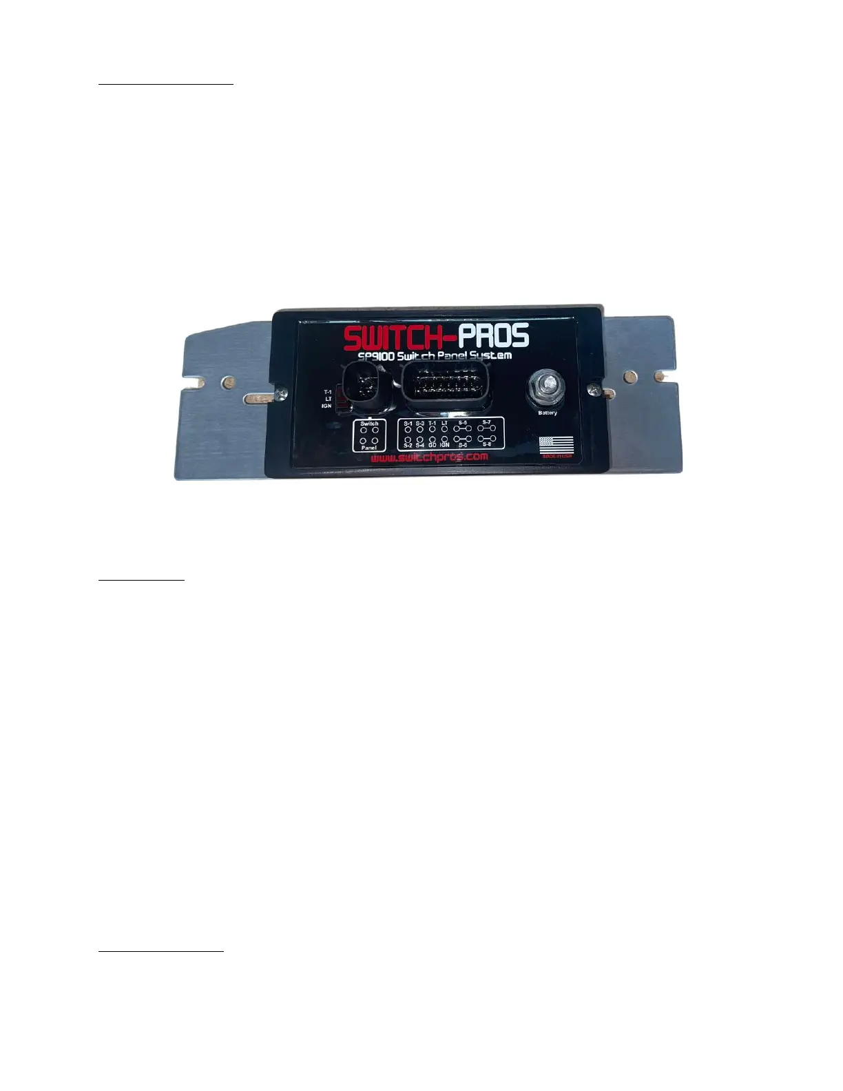
2. Power Module
2.1 Mounting Guidelines
• Mount within 2’ of the vehicle’s battery, as that is the standard length of the Battery Cable.
• Mount in a vertical position, with the connectors facing outward, rather than upward, so
water cannot accumulate on the connector seals.
• Recommended mounting locations include: on the firewall near the fender, or on the fender.
o The Power Module is manufactured with automotive rated electronic parts, with a
temperature rating of -40°C to 125°C.
o Note: Do not mount the power module in a location near the engine exhaust, where
temperatures will exceed the rating.
o Note: The App will display the temperature of the Power Module, so it can be monitored.
• To use the supplied, universal mounting plate, use 2 M4 nuts and bolts, found in the supplied
hardware kit.
• Note: The Communications Cable that connects the Switch Panel and Power Module will be
the last connection made.
3. 16-Pin Output Harness
3.1 Output Wires
• Switches 1 - 4 have a single, 14 AWG, wire, and are rated at a maximum of 20 Amps.
• Switches 5 - 8 each have 2, 14 AWG, wires, and are rated at a maximum of 35 Amps.
o Note: BOTH wires must be tied together to create a 35A circuit.
o Note: The wires may be split, to power separate accessories, at a maximum of 17A for each wire, but
both accessories will come on and off together, since they are connected to the same Switch.
• The output wires are 14 AWG.
o Note: 14 AWG wire is sufficient for a load up to 20A, with a run no longer than 6 feet. For longer
runs at max current, it is recommended to use a larger gauge wire, such as 12 or 10 AWG.
o Note: To figure out the current draw of an accessory rated in Watts, simply divide power rating of the
accessory by the operating voltage. For example, a 300W light bar, running at 12V: 300W/12V = 25
A.
• Connect the 14 AWG output wires to the positive lead of the accessory. Connect the Ground wire of the
accessory to a Ground stud on the vehicle’s frame, or the negative terminal of the battery.
• The output wires switch a 12V signal. They will not switch a Ground signal.
• Current limits for the Switches can be adjusted, in the App, in 5A increments. We recommend setting the
overcurrent protection 15 - 20% higher than the maximum current draw of the accessory.
o Note: Do not set current limits too low. When battery voltage decreases, amperage draw increases,
and the system will shut off any accessory trying to operate above the maximum amperage for that
circuit.
3.2 Black Ground Wire
• The Black Ground Wire is a single, 18 AWG wire, with a blue lug crimped on the end.
• The Black Ground Wire should be connected directly to the negative terminal of the battery.
o Note: It is acceptable to shorten or lengthen this wire, depending on distance between the Power
Module and Battery.
 Loading...