Pg. 1 1/2018
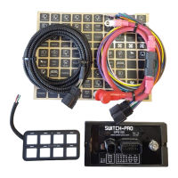
SP9100 8-Switch Programmable Switch Panel Power System
Read this before installing!
1. You MUST connect the Lt. Blue Ignition sense wire to an ignition or accessory source for the switches to operate.
The default setting for all switches is “Ignition” controlled.
2. Connect the black ground wire directly to the Negative terminal of the battery. DO NOT connect to frame ground
studs or ground distribution studs.
3. Do not connect any other power feeds to the power module’s power stud.
4. Do not use the SP9100 to control a winch. Use the winch manufacturer’s supplied device
5. Do not modify the switch panel communications cable.
6. Recommended installation of Power Module is the VERTICAL position, so that water runs off and does not
collect on the top of the connector, or face of the module. Failure to do so will compromise the integrity of the
water proof rating (IP67), and affect warranty coverage.
7. The use of a Terminal Block IS NOT RECOMMENDED, as wires are left exposed and susceptible to water and
corrosion.
Overview
The SP9100 Switch Panel Power system is a solid state switching system that is fully programmable and features Apple
and Android Bluetooth accessibility and RGB backlighting.
The switch panel has 8 switches and one programming switch. A red led indicates when the switch panel is in
programming mode and a blue led indicates when a Bluetooth connection is present.
The power module has 8 outputs, switches 1 – 4 are rated at 20A, and switches 5 – 8 are rated at 35A.
The power module also has 3 inputs, one Ignition sense, one Lights sense that can also be configured as an external trigger
input Trigger 2, and one dedicated external trigger input Trigger 1.
The Trigger 1 and Trigger 2 inputs can be configured to sense active high or active low inputs. Both trigger inputs can
switch on up to 4 outputs. The power module has 3 led indicators to display the status of each input.
The switch panel has an idle mode and a sleep mode. The idle mode will start after 1 minute of inactivity with a current
draw of 5.5mA. The sleep mode will start after 8 hours (default) of inactivity which is adjustable in the App with a current
draw of 3.0mA. If switch panel backlighting is on, the system WILL NOT enter sleep or idle mode.
The idle mode will activate when all switches are off, no Bluetooth connection, no Ignition, light, or trigger inputs.
In idle mode, the system will still respond to all inputs including switches and Bluetooth.
The sleep mode will activate when all switches are off, no Bluetooth connection, no Ignition, light, or trigger inputs.
In sleep mode Bluetooth is disabled, but all other inputs (except lights input), including switches will wake up the system.