Pg. 4 1/2018
3. Connecting Accessories
Identify which accessories you will be powering with your Switch Panel Power System. Remember that Switches 1-4 are
limited to 20 amps, and switches 5- 8 are limited to 35 amps. Therefore, the accessory with the largest draw should be
connected to Switches 5- 8.
To figure out the current draw of a load rated in watts, simply divide power rating of the accessory by the operating
voltage. For example a 300 Watt light bar running at 12V, that would be: 300W/12V = 25 A.
Keep in mind that for a lower voltage the current draw will be higher. If the vehicle’s voltage drops down to 10V, the
current will increase to 30 A. In this case it would be wise to set the over current limit to 35 A (using App).
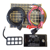
Connect the accessory directly to the output wires of the power module. The SP9100 switches 12V to the accessory.
The power harness uses 14 AWG wires to power accessories. That is good for a load up to 20 A with a run no longer than
6 feet. For longer runs at max current it is recommended to use a larger size wire like 12 or 10 gauge.
For switches 5 – 8 with the higher amperage capacity both output wires MUST be connected together and spliced into a
larger size wire such as 12 or 10 gauge.
Connect the power module output wire to the positive wire of the accessory. Connect the ground wire of the accessory
directly to ground, either a ground stud on the vehicle’s frame or to the negative terminal of the battery.
Current limits can be adjusted in the App in 5A increments. We recommend setting the overcurrent protection 15% to
20% higher than the maximum rated current of the accessory.
4. Control Wires
There are 3 control wires for external control of accessories and switch panel backlighting illumination.
IGNITION Input, Lt. Blue wire. Enables ignition programmed switches and turns on backlighting to 70%.
Connect this wire to an ignition or accessory 12V source. Use a T-tap to make the connection or solder and seal.
When the Lt. Blue Ignition wire senses 12V, switches that are programmed to be “ignition controlled” are
enabled. When the ignition signal turns off, all “ignition controlled” programmed switches, and their outputs, will
turn off.
When the Lt. Blue ignition wire senses 12V, the red led indicator marked Ignition on the power module will
illuminate.
The other option is to program individual switches to be “battery controlled”. When “battery controlled,” the
switches will operate at all times.
Note: A Bluetooth connection overrides the Ignition input. All Ignition programmed switches will operate if the
Ignition is Off, but a Bluetooth connection is present. This is so you aren’t required to leave keys in the ignition
while remotely controlling your accessories.
LIGHTS Input/T2, White wire. Turns on switch panel backlighting to user set level. Trigger 2 input if enabled.
Connect this wire to a parking light signal or a side marker light signal. Use a T-tap to make the connection or
solder and seal. This wire is used to dim the switch panel backlighting for night time lighting. The backlighting
and switch indicator led brightness intensity is set by pressing the programming switch (located behind the
SWITCH-PRO logo) on the switch panel 3 times. Switches 1 and 2 adjust the led switch indicator brightness and
switches 7 and 8 adjust the backlighting intensity. Once the intensities are set, press the program switch again to
exit.
On Side by Side UTV vehicles, like Razors and CanAm’s, that do not have parking lights, connect the White
“Lights” wire to the Lt. Blue “Ignition” wire. Then connect both to an 12V ignition or accessory source.
Trigger 1 input, Pink wire. External trigger input to turn on up to 4 outputs.
Connect the Pink wire to an external trigger, it can be a high beam signal, reverse light signal, or a dome light
signal to give a few examples. Use a T-tap to make the connection or solder and seal.
For example, if connected to the high beam signal, when turning on the high beams on the vehicle, up to 4 outputs
of the switch panel will also turn on.
The function must be enabled in the App. The function can be turned on and off through the switch panel, to
switch between off-road and street driving, by holding down the programming switch and pressing switch 7.
Both Trigger 1 and Trigger 2 inputs can be programmed to trigger on an active high or active low signal in the
App.
 Loading...