Pg. 3 1/2018
Switch panel harness connector removal
When installing the switch panel communications harness it might be necessary to remove the black MOLEX 4-pin
connector in order feed the harness through tight spaces. Follow the procedure below to remove the terminals. Check
the 4-pin Harness Connector pin-out drawing above for proper wiring.
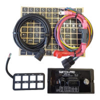
Step 1: Insert a small screwdriver (max. width of 3.00mm (.118”) into the designated pry point of the TPA.
Step 2: Using the housing as a pivot point, gently pry out the TPA until it reaches pre-lock position.
The TPA should never be fully removed from the connector housing. Excessive force can damage the TPA
Step 3: Using the 1.50mm (.059”) service tool #63813-1500, or a paper clip, insert the tip into the terminal service hole
adjacent to the terminal to be serviced. Push straight down gently and apply pressure to release-locking finger. This
motion will release the locking finger, “picking” is not required. A click can be felt once fully engaged. Do not insert the
service tool at an angle, this may cause damage to the terminal.
Gently pull the wire to be released. If the terminal resists, the service tool may not be fully engaged.
Step 3 Correct Terminal Orientation
Step 4: When re-installing the terminal make sure the TPA is in the released position, and the orientation of the
terminal is correct, see pic above, Once the terminal is seated, push down on the TPA applying even force.
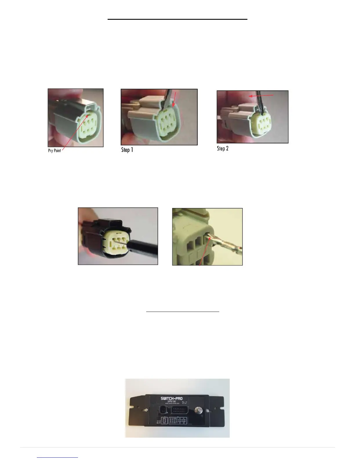
2. Installing the Power Module
The power module should be mounted close to the vehicle’s battery using the supplied 2 feet long battery cable. The
power module is manufactured with automotive rated electronic parts, with a temp rating of -40 C to 125 C. Care must be
taken though not to mount the power module in a location near the engine exhaust where temperatures will exceed the
rating. Usually on the firewall near the fenders, or along the fenders is a good location. Do Not mount the power module
above the engine on the fire wall. The App will display the temperature of the power module so it can be monitored.
Mount the power module in a vertical position, so that water can’t accumulate on the connector seals. Failure to
do so may result in limited or no warranty coverage. The power module can be mounted to the supplied mounting
plate using 2 M4 nuts and bolts (supplied). See drawing below:
 Loading...