Pg. 2 1/2018
Installation
Disconnect the negative battery lead from the vehicle’s battery before proceeding with installation, and to avoid
damage to the electrical system!
See the last page for vehicle specific installations.
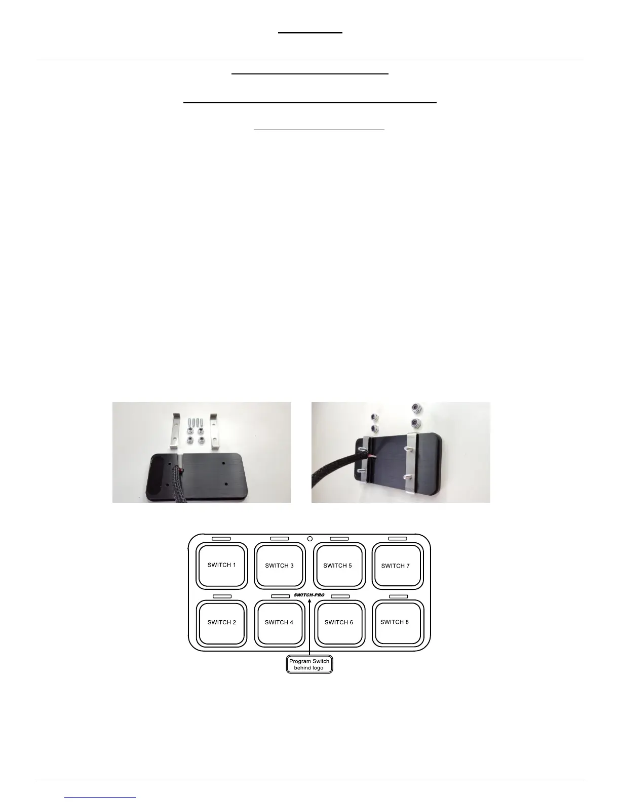
1. Installing the Switch Panel
Identify which accessories you will be powering with your Switch Panel Power System. Remember that Switches 1-4 are
limited to 20 amps, and switches 5-8 are limited to 35 amps. Therefore, the accessories with the largest draws should be
connected to switches 5-8.
Once your outputs are determined, select the appropriate legends from the Switch Legends sheet, and affix them to the
panel. Center each legend inside the grey border of each switch. Should you need to remove a legend, we suggest you use
a straight pin and lift at a corner until you can grasp it with your fingers. DO NOT dig at the graphic overlay, as the mem-
brane could be damaged.
The switch panel can be mounted to a flat surface by drilling holes for the 6-32 mounting studs, and a hole for the harness
feedthrough, then screwing the threaded studs into the switch panel and securing the switch panel with the supplied 6-32
nuts.
For a bezel style mount, cut a rectangular opening measuring 3.865” x 1.865” with a corner radius of 0.237”. See
Template on the last page.
Then screw the four 6-32 threaded studs into the backside of the switch panel and tighten. Place the switch panel into the
opening and slide the two mounting brackets over the studs. Then secure the mounting brackets with the 6-32 nuts. Do not
over tighten the nuts.
Connect the switch panel harness to the switch panel, then plug the black sealed connector into the power module
connector. If the harness needs to be routed through a tight space in the firewall, the black 4-pin connector’s pins can be
removed, see directions on the next page.
 Loading...