Rev 2.0 Jan. 2024
4
3.3 Input Wires
• Light Blue Ignition Wire – When this wire senses voltage, ignition programmed switches become
operational, and the Switch Panel backlighting illuminates.
o Tap this wire into an ignition or accessory switched, 12V source, using an Add-a-Circuit, fuse tap, or
similar apparatus.
▪ Note: Typically, fuses in the fuse box, labeled IGN or ACC, are correct places to tap this wire in.
The right source has 12V when the key is in ignition or accessory mode and ceases to have 12V
when the key is in the off position.
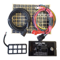
▪ Note: The supplied Add-a-Circuit will come with a low amperage fuse. Insert the supplied fuse
into the slot furthest from the prongs. Use the fuse, from the fuse box slot where the Add-a-
Circuit will be inserted, to fill the slot closest to the prongs. Then, insert the Add-a-Circuit into
fuse slot, from which you removed the factory fuse, and crimp the input wire to the blue butt
splice.
Add-a-Circuit Add-a-Circuit with fuse inserted
▪ Note: If the backlighting is always illuminated, even with the vehicle’s ignition off, the Add-a-
Circuit is tapped into a fuse that is always hot, and needs to be moved to another fuse.
▪ Note: When the Light Blue Ignition Wire senses 12V, the red LED indicator, labeled IGN, on
the Power Module, will illuminate.
▪ Note: If you want certain switches to always be operational, whether the key is on or off,
program those individual switches to be “Battery” in the App Settings (See Section 7.1).
▪ Note: A Bluetooth connection overrides the Ignition input. All Ignition programmed switches
will operate if the Ignition is off, but a Bluetooth connection is present. This allows the operator
to remotely control accessories, without being required to leave the ignition on.
• White Lights/T2 Wire – When this wire senses 12V, it dims the Switch Panel backlighting, just as dash
lights dim at night. The backlight and LED indicator intensity, when the White Lights/T2 Wire is sensing
12V, is adjustable through the LED Backlight App Settings (See Section 7.2).
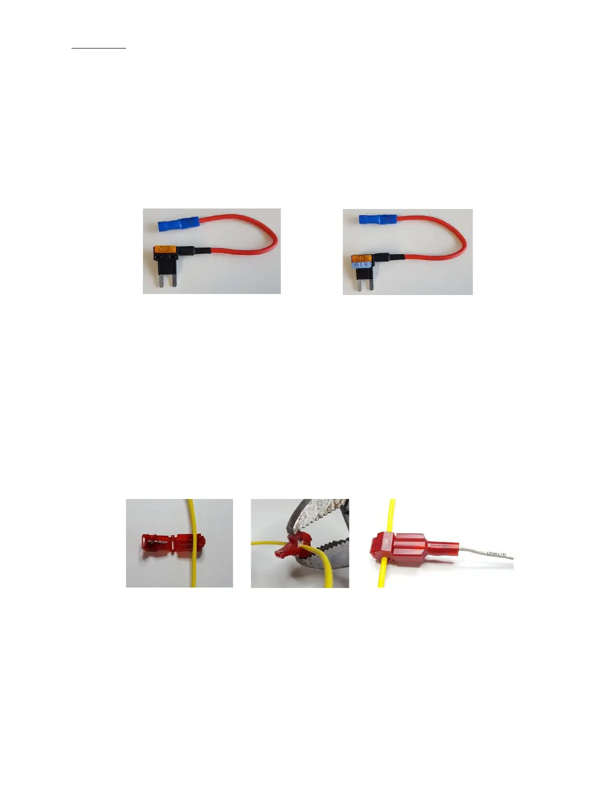
o Tap this wire into a parking light, side marker light, or other source that you want the Switch Panel
backlighting to dim with.
Place wire in t-tap Crimp Plug in blade connector
▪ Note: This feature is optional. It is not required to be wired up for operation.
▪ Note: The Switch Panel backlighting is only adjustable when the White Lights/T2 Wire is
sensing 12V.
▪ Note: If the Switch Panel backlighting remains illuminated after the key is in the off position, the
White Lights/T2 Wire may still be sensing 12V.
▪ Note: When the White Lights/T2 Wire senses 12V, the red LED indicator, labeled LT, on the
Power Module, will illuminate.
• Pink Trigger 1 Wire – This wire allows an external source to trigger multiple Switch-Pros outputs.
o Tap this wire into an external trigger, such as a high beam signal, reverse light signal, dome light
signal, temperature gauge, etc.
▪ Note: This feature is optional. It is not required to be wired up for operation.
 Loading...