Rev 2.0 Jan. 2024
5
o Up to 4 outputs can be programmed to come on with the trigger.
▪ Note: Outputs programmed to be turned on with the External Trigger can still be turned on and
off through the Switch Panel.
▪ Note: This wire can sense a 12V (Active High) or Ground (Active Low) signal. The trigger
activation method can be changed in the External Trigger App Settings (See Section 7.8).
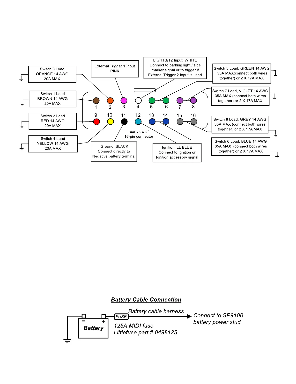
4. Battery Cable
4.1 The Battery Cable is a 2.5’, 4 AWG welding cable, with a 125A in-line fuse, that connects to the stud on the
Power Module and the positive terminal of the battery.
• The Battery Cable may be installed, once the Power Module and Switch Panel are mounted, the 16-Pin
Output Harness is plugged in, and the Black Ground Wire is connected directly to the negative terminal
of the battery. The Communications Cable should not be plugged in yet.
• Note: Before connecting the Battery Cable to power, be sure the Light Blue Ignition Wire is not sensing
voltage.
o If the Light Blue Ignition Wire senses voltage before the Battery Cable is connected, the Switch
Panel Bluetooth will temporarily lock up, and the Programming Light, in the top, center, of the
Switch Panel, will be illuminated blue. To unlock the Bluetooth, unplug the Communications Cable,
either from the back of the Switch Panel or the Power Module, for 30 seconds. When the
Communications Cable is plugged back in, the Bluetooth capability will be available again and the
Programming Light will no longer be illuminated.
• Connect the longer section of the Battery Cable to the Power Module first, then connect the shorter side,
with the fuse holder, directly to the positive terminal of the battery.
o Note: Do not connect any other power feeds to the Power Module stud.
o Note: The system is only compatible with a 12V battery.
• Use a 9/16” socket to tighten the nut onto the Power Module stud.
 Loading...