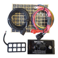
5. Communications Cable
5.1 The Communications Cable is a 10.5’, specialty cable, with shielding and a soldered drain wire, which
connects the Switch Panel and Power Module. The smaller, white, connector plugs into the wires off the
back of the switch panel, and the larger, black, connector plugs into the Power Module. This cable is
typically fed through the engine firewall.
• Note: Do not alter the length of the cable. If you need a custom length, please contact our Sales
Department at Sales@Switch-Pros.com or 949-581-2991.
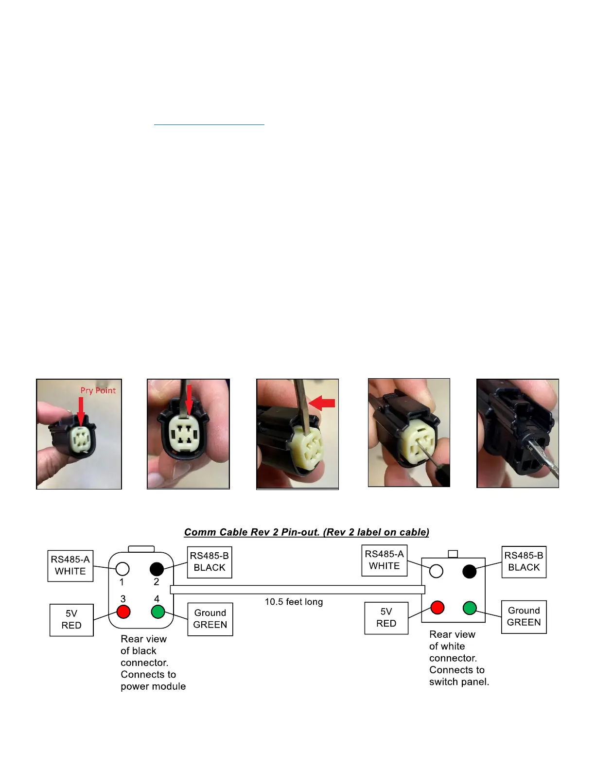
• To feed the Communications Cable through a tight space, it may be necessary to remove the black 4-pin
connector. Do not unpin the white connector. It is not serviceable.
o Note: Before un-pinning, note the original color pin-out prior to removing the connector.
o Step 1: Insert a small screwdriver (max. width of 3.00mm (.118”)) into the pry point
of the Terminal Position Assurance (TPA).
o Step 2: Using the housing as a pivot point, gently pry out the TPA until it reaches
pre-lock position.
▪ Note: The TPA should never be fully removed from the connector housing.
o Step 3: Using the 1.50mm (.059”) MOLEX service tool #63813-1500, or a paper clip (end must be
rounded), insert the tip into the terminal service hole, adjacent to the terminal to be serviced. Push
straight down gently and apply pressure to release-locking finger. This motion will release the
locking finger, “picking” is not required. A click can be felt once fully engaged.
o Step 4: Gently pull the wire to be released.
▪ Note: If the terminal resists, the service tool may not be fully engaged.
▪ Note: Do not insert the service tool at an angle, this may cause damage to the terminal.
o Step 5: When re-installing the terminal, make sure the TPA is in the released position, and the
orientation of the terminal is correct. Once the terminal is seated, push down on the TPA, applying
even force.
 Loading...