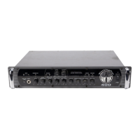
550x • 15
In the LINE position, all front panel controls–including the Aural Enhancer, SubWave™, and EQ controls–are functional except
the Master control, and the signal is essentially the same as that heard through your speaker system. If you are using an exter-
nal effects device in the effects loop, that signal will also be present when in the LINE position (dictated by the setting of the
Effects Blend control on your 550x). When in this position, the output level will be affected by the Gain control on the front
panel as well as the XLR Pad control. It's worth noting that changing the level of the Gain control will affect the signal present at
your speakers, the Effects Send jack, and the Balanced Output, while the XLR Pad control affects the level present at the
Balanced Output only. For this reason, it's usually better to set your Gain control in accordance with the directions in the "Gain
Control" previously listed in the "Front Panel Features" section of this manual, and to use the XLR Pad control to set the level
specifically for the Balanced Output.
The third position for this switch is the DIRECT + SUB position. In this position, the signal present at the Balanced Output jack is
the same as when in the DIRECT position, with one important exception: the SubWave™ is present. What's the benefit of this
setting?
We've found that most people who use effects pedals prefer to use them in front of the amplifier. In other words, they run their
bass into the effect pedal's input, then from the effect pedal's output into the front of their amplifier. In live applications where
sound reinforcement is required, often times the front-of-house engineer will take a direct signal from the bass itself (via either
a direct box, or the Balanced Output of your amp set to the DIRECT position) and use that signal as the main bass sound to the
house P.A. This way, if the bassist sets the amplifier's EQ controls in a way to his liking, but in a manner not conducive to a
good bass sound for the house P.A., the front-of-house mixing engineer still has a nice, flat bass signal to work with, and then he
can EQ the bass sound for what's best in the room. And, more relevantly, he would still get the sound of any effects pedal that
was placed in front of the amplifier.
The DIRECT + SUB position provides this exact function for the Balanced Output. It always contains the sound of your bass sig-
nal just after the first tube stage, and will also contain the SubWave™ effect when engaged without also sending EQ settings
that may not be right for the house P.A. (or a studio mixing console). You can always include all of your EQ settings (plus the
SubWave) at the Balanced Output by setting the three-position switch to the LINE position. But thanks to the DIRECT + SUB
position of this switch, it's not a necessity that you do so just because you want the SubWave™ present at the Balanced
Output.
NOTE: You can still use the SubWave™ Level control to set the amount of sub-octave effect present
at the Balanced Output when in the DIRECT + SUB mode; however, it will also affect the level
present at the speaker outputs as well. Also, though the Gain control will not affect the level of the
"clean" bass signal present at the Balanced Output when in DIRECT + SUB mode, it WILL affect the
level of sub-octave present. This is normal, and occurs because the SubWave™ circuit is located
after the first stage of the preamp tube and is blended back into the signal specifically for this
special mode of the three-position switch. We recommend that you set the Gain and SubWave™
Level controls in accordance with previously mentioned instructions, and the gain structure should fall
into place fairly automatically.
Wiring for the XLR jack at the Balanced Output is as follows:
Pin 1 = ground, Pin 2 = + (plus), Pin 3 = - (minus)
(American Standard)
NOTE: Turn off transients appear at the Balanced Output when the amplifier is shut down. We
recommend that equipment being used in conjunction with the Balanced Output be turned down, off,
or disconnected BEFORE the 550x is turned off.
 Loading...
