Do you have a question about the SWR SPELLBINDER BLUE and is the answer not in the manual?
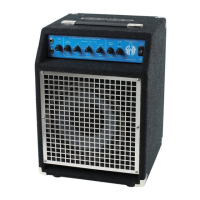
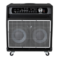
The SWR Spellbinder Blue is a bass amplifier, model number PR 761, designed and manufactured by Fender Musical Instruments Corporation. It integrates a studio-reference tube preamp with a 160W digital power amplifier, all housed within a compact and relatively lightweight cabinet. The amplifier is available in several voltage configurations, including 120V (US), 240V (AUS), 230V (UK), 230V (EUR), and 100V (JPN).
The Spellbinder Blue serves as a complete bass amplification solution, combining a versatile preamp section with a powerful Class D amplifier and a speaker cabinet. The preamp features a tube gain stage (V1-A and V1-B) and offers extensive tone-shaping capabilities. It includes a GAIN stage (U7A) with up to 1.1X gain, a PHASE reversal stage (U5A) to change the channel phase by 180°, and an EQ IN/OUT Switch (S6) to select between a passive Aural Enhancer circuit (classic SWR bass amplifier circuit) or an active attenuation circuit (U5B). The EQ circuitry, comprising U9A&B, U10A, and U13B, allows for boosting or attenuating each frequency range by +/-15dB, with a flat response when all level knobs are at their center-detent position.
The signal path also includes an Effects Send buffer (U11A), an EFFECTS BYPASS switch (S7), and an EFFECTS BLEND pot (R91) that mixes the Send and Return signals before a -12dB/octave high-pass filter (U10B). A compressor chip (U8B) with U15A provides up to 20dB of compression, controlled by the COMPRESSION pot (R92). The MASTER Volume control (R93) at U12A offers a maximum gain of 3.5X and, along with the inverted signal at U12B, acts as a gain buffer for the power amp. Preamp Clip Detect circuits monitor various stages, illuminating a Clip LED if overload thresholds (approximately 12V) are exceeded. A MUTE circuitry, engaged by S8, mutes the speaker output (on the Power Amp PCB) and the Balanced Line Output (on the Rear Panel PCB).
The Rear Panel PCB, connected to the Preamp PCB via a 12-circuit ribbon cable, handles various outputs. The TUNER_RP signal feeds the tuner output buffer (U1B) and the DIRECT signal for the BALANCED LINE OUTPUTS. The DIRECT or LINE_RP signal is selected by S1 and muted by FETs Q1 and Q2. It is then buffered by U1A, where the PAD control (R4) sets the output level. A balanced line driver (DRV134, U2) produces a high-quality signal for both the balanced 1/4" (J3) and XLR jack (J7). The HEADPHONE output (J5) uses paralleled 4560 opamps for high current drive.
The speaker crossover components are located on the XOVER PCB inside the speaker cabinet. It includes a -6dB/octave low-pass filter (L1) for the 10" speaker and a -6dB/octave high-pass filter (C3) for the Horn. A 50W L-PAD controls the Horn volume.
The power amplifier is a Bang & Olufsen 50ASX2 module, providing 160 Watts into 4Ω with less than 1% THD. This module also generates a low voltage +/-25V supply (P103) for the Ancillary Power Supply. The Ancillary Power Supply, a non-serviceable switching module, takes the +/-25V AUX Supply from the 50ASX2 and generates +300V (Tube), 12.6V (Tube Heater), and +/-15V (Preamp Op amps).
The Spellbinder Blue is designed for professional bass players, offering a comprehensive set of features for live performance and studio recording. Its versatile preamp allows for a wide range of tonal adjustments, from clean and articulate to warm and overdriven, thanks to the tube stages and extensive EQ. The effects loop and blend control provide flexibility for integrating external effects. The balanced line output (XLR and 1/4") with a PAD control and ground lift ensures high-quality signal delivery to mixing consoles or recording interfaces. The headphone output allows for silent practice. The integrated 10" Neodymium speaker and Super-Tweeter provide a full-range sound, with the L-PAD allowing for precise control over the tweeter's volume.