15. ELECTRICAL EQUIPMENT
15-12
Electrical System Circuit Inspection
Pulse Generator/Exciting Coil
Remove body cover.
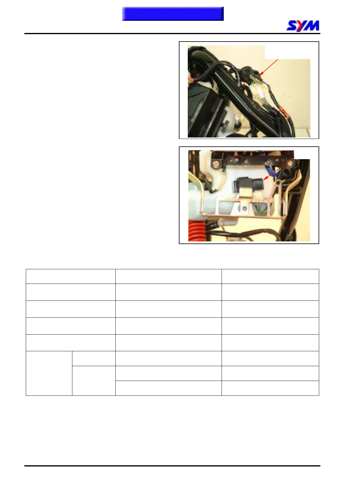
Disconnect alternator connector.
Resistance Measurement: (20℃)
Pulse generator coil (blue/yellow - ground):
50~200Ω
Exciting (yellow - ground): 400~800Ω
CDI Electrical System Circuit Inspection
Remove body cover.
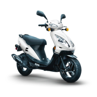
Disconnect the CDI set connector, and check its
circuit to diagnosis related ignition components.
CDI Electrical System Circuit Inspection
ITEM Measure at:
Standard (at 20℃)
Main Switch (compatible
with JET 50/100)
Black/white-green Continuity as main switch OFF
Main Switch (compatible
with JET EURO 50/100)
Black/ Blue -green
Continuity (battery voltage) as
master switch ON
Exciter Coil (compatible
with JET 50/100)
Black/Red-Green 400 ~800Ω
Pulse Generator Blue/Yellow-green 50 ~200Ω
Primary Black/yellow-green 0.21Ω±10%
Green-high voltage cable -w/o Cap 3~5KΩ
Ignition Coil
Secondary
Green-high voltage cable - w/ Cap 7~12KΩ
y If above checks are in normal but spark plug is still no spark. Then it probable causes from CDI set
or high voltage coil.
y If abnormal circuits are found in above checks, at first check all items, and then check each item
one by one.
AC generator
harness connector
C.D.I.
This chapter Contents