8
Quick Start Guide
6408 216th Street SW | Mountlake Terrace, WA 98043 USA
T +1.425.778.7728 F +1.425.778.7727 | www.symetrix.co
Rear Panel
NOTE:
Detachable terminal blocks connectors are designed for use with bare wire. Do not tin stranded wires before inserting them into the connectors.
Rear Panel
Item Description Comments
Power Input Lockingpowerplug Accepts power from Symetrix power supply part number 12-0002-A (100-240 VAC,
50-60 Hz, 25 Watts max). Connect only to a grounded power outlet.
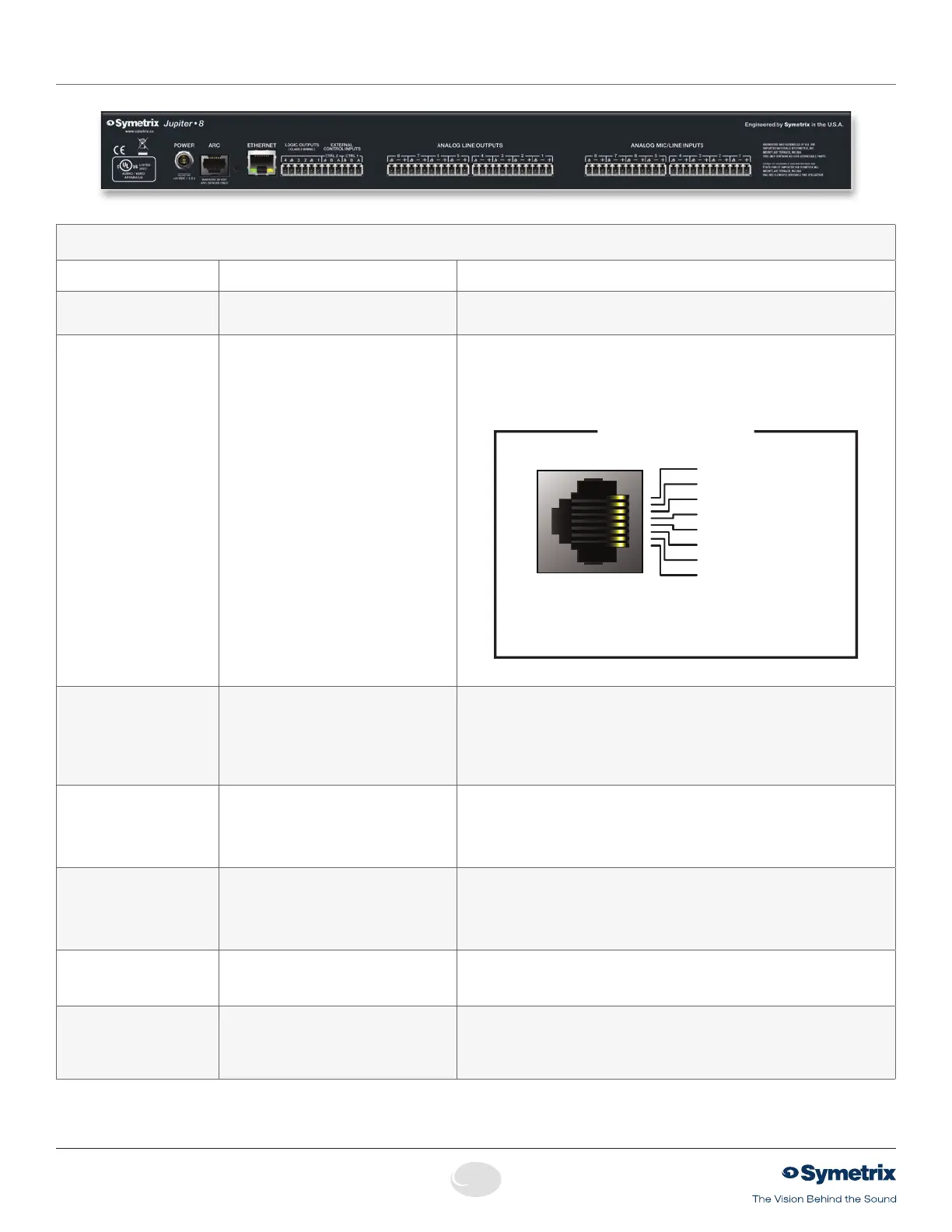
ARC RJ45 jack Distributes power and RS485 data to one or more ARC devices. Uses standard
straight-through UTP CAT5 cabling.
1
!
Warning! Refer to the RJ45 Warning for compatibility information.
Individual wires may be broken out according to the pinout diagram below for use
with an ARC-PS or longer RS485 runs with local ARC powering.
1
2
3
4
5
6
7
8
1
2
3
4
5
6
7
8
1 • AUDIO
(+)
2 • AUDIO
(-)
3 • COMMON GROUND
4 • RS-485 DATA
(
A
)
5 • RS-485 DATA
(
B
)
6 • COMMON GROUND
7 • POWER
(
+V
)
8 • POWER
(
+V
)
Note: The ARC Audio line may be grounded at the
Symetrix rack-mount device and the ARC wall panel
to provide additional distance.
ARC PORT PINOUT
PortSettings:38.4kbaud,8databits,1stopbit,noparity,noflowcontrol.
Ethernet RJ45 jack CommunicationsinterfaceforJupitersoftwarerunningonthehostPCaswellas3rd
partycontrolforsystemssuchasAMXorCrestron.Usesstandardstraight-through
UTP CAT5 cabling. Features auto-crossover sensing for direct device-to-device con-
nections.
For3rdpartycontrol,refertothecontrolprotocoldocumentavailableontheSymetrix
web site or within the Jupiter software help file.
Logic Outputs (1–4)
Two(2)3-pin3.81mmterminalblocks Four(4)logicoutputswithtwo(2)pairedcommongroundpins.LogicOutputsgo
low (0V) when active, and are internally pulled high (5V) when inactive and can
driveexternalLEDindicatorsdirectly.PurposeconfiguredbytheExternalController
Wizard,abletofollowmostbuttonsandLEDsinsoftware.Polaritymaybeinvertedin
software.
External Control Inputs
(CTRL 1 and 2)
Two(2)3-pin3.81mmterminalblocks Allows real-time control of any volume using standard 10k Ohm linear potentiom-
etersormutesandpresetsusingstandardcontactclosures.Mayalsobeusedfor
emergency system integration. Purpose configured by the External Controller Wizard.
Each connection accommodates one potentiometer or two switches. Uses standard
shielded twisted pair cabling.
Analog Line Outputs
Four(4),eight(8)orfour(4)3-pin3.81
mm terminal blocks on Jupiter 4, 12 or 8
respectively.
Four (4) or eight (8) balanced analog line level audio outputs, individually software-
selectablelevelsof-10dBVor+4dBu.
Analog Mic/Line Inputs Four(4),eight(8)ortwelve(12)3-pin3.81
mm terminal blocks on Jupiter 4, 8 or 12
respectively.
Twelve (12), eight (8) or four (4) balanced analog audio inputs with individually
software-selectablephantompowerandlevelof-40dBuor+4dBu.
Note:Input4maybeswitchedinternallytotheARCAudioinput.Modeisconfigured
by the inputs panel in the software.
 Loading...