5-5 L2200EA
10. Sub-Brightness Adjustment
Purpose: To get proper brightness.
Symptom of Misadjustment: If Sub-Brightness is
incorrect, proper brightness cannot be obtained by
adjusting the Brightness Control.
Note: IQW Setup level --- 7.5 IRE
Use service remote control unit
1. Enter the Service mode. (See page 5-1)
Then input IQW signal from RF Input.
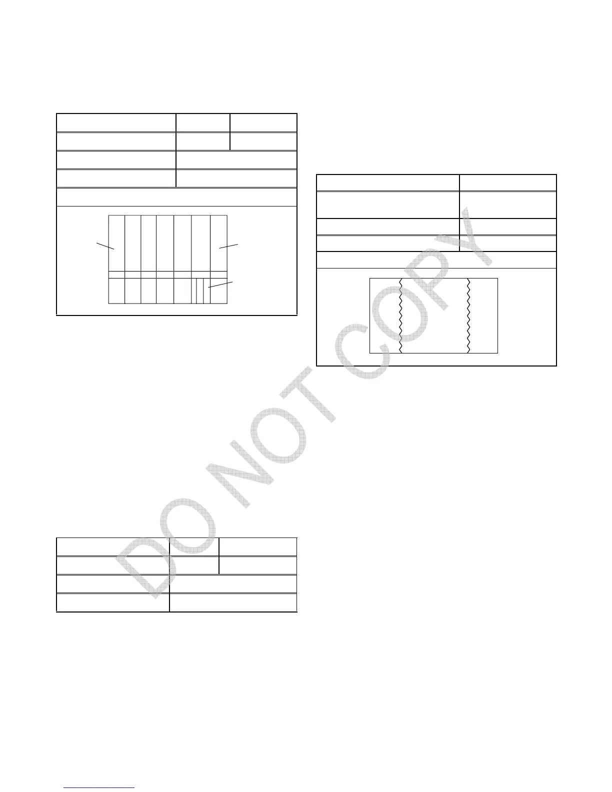
2. Press "MENU" button on the service remote control
unit and Select "BRT" mode. (Display changes
"BRT," "CNT," "CLR," "TNT," "V-TINT" and
"SHARP" cyclically when "MENU" button is
pressed.) Press "CH o / p" buttons so that the bar
is just visible (See above figure).
3. Turn the power off and on again, using the main
power button on the TV unit.
11. Focus Adjustment
Purpose: Set the optimum Focus.
Symptom of Misadjustment: If Focus Adjustment is
incorrect, blurred images are shown on the display.
Note: Focus VR (FBT) --- Main CBA,
FBT= Fly Back Transformer
1. Operate the unit more than 30 minutes
2. Face the unit to the East and degauss the CRT us-
ing a degaussing coil.
3. Input the Monoscope Pattern.
4. Adjust the Focus Control on the FBT to obtain
clear picture.
The following 2 adjustments normally are not
attempted in the field.
They should be done
only when replacing the CRT then adjust as a
preparation.
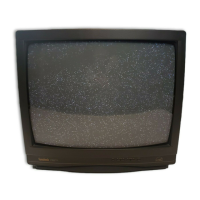
12. Purity Adjustment
Purpose: To obtain pure color.
Symptom of Misadjustment: If Color Purity Adjust-
ment is incorrect, large areas of color may not be
properly displayed.
1. Set the unit facing east.
2. Operate the unit for over 30 minutes before adjust-
ing.
3. Fully degauss the unit using an external degauss-
ing coil.
4. Loosen the screw on the Deflection Yoke Clamper
and pull the Deflection Yoke back away from the
screen. (See Fig. 6)
5. Loosen the Ring Lock and adjust the Purity Mag-
nets so that a red field is obtained at the center of
the screen. Tighten Ring Lock. (See Fig. 5, 6)
6. Slowly push the Deflection Yoke toward the bell of
the CRT and set it where a uniform red field is ob-
tained.
7. Tighten the clamp screw on the Deflection Yoke.
Adj. Point Mode Input
CH o / p buttons RF IQW
M. EQ. Spec.
Pattern Generator See below
Figure
Adj. Point Mode Input
Focus Control RF Monoscope
M. EQ. Spec.
Pattern Generator See below
White
Black
Fig. 4
This bar
just
visible
Adj. Point Input
Deflection Yoke,
Purity Magnet
*Red Color
M. EQ. Spec.
Pattern Generator See below.
Figure
GREEN RED BLUE
Fig. 5