Note
Each Digital IO needs to be configured as a Digital Input or Output via object 0x2210 (“GPIO”).
The object can also be used to activate a pull-down resistor.
Changes may require to powercycle the servo drive.
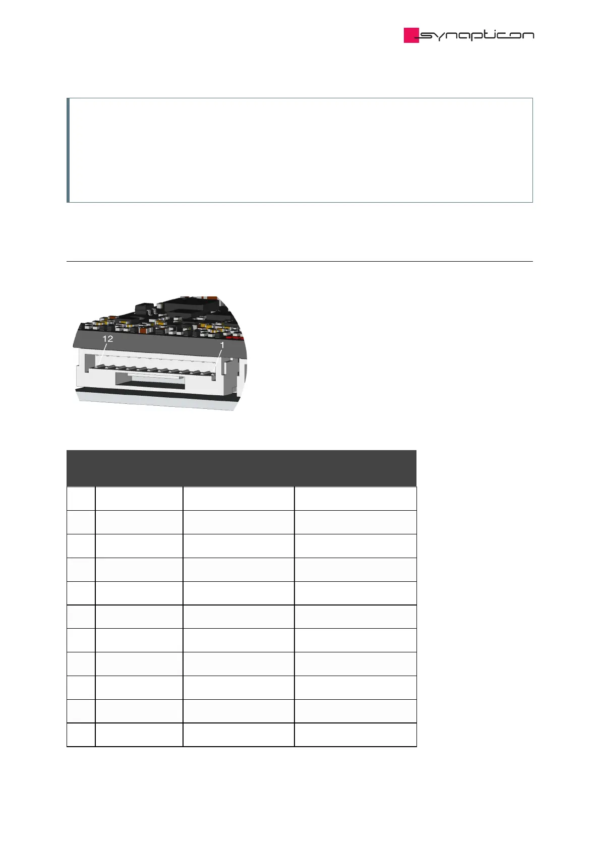
1.4.1.3.4 Analog IN
Pin
#
Default Setting * Object Mapping
1 –
2 Analog Input 1 - Connect to Ground **
3 Analog Input 1 + Single-ended 0-10 V Analog input 1 (0x2401)
4 Ground
5 Analog Input 2 - Connect to Ground **
6 Analog Input 2 + Single-ended 0-10 V Analog input 2 (0x2402)
7 5 V ***
8 10 V ****
9 Analog Input 3 - Differential ±5 V Analog input 3 (0x2403)
10 Analog Input 3 + Differential ±5 V Analog input 3 (0x2403)
11 Analog Input 4 - Differential ±5 V Analog input 4 (0x2404)