Master Language is English Hot Runner System Installation Guide SVC-17-0001_EN-Rev11
RESTRICTED: Property of Synventive. - 391 - All rights reserved. Errors and omissions excepted
For limited third party distribution based on need and intended use. © 2019 Synventive Molding Solutions
H O T R U N N E R T E C H N O L O G Y
Hot Runner System Installation Guide
Service and Maintenance / Single Axis Valve Gate Nozzle 16SVH
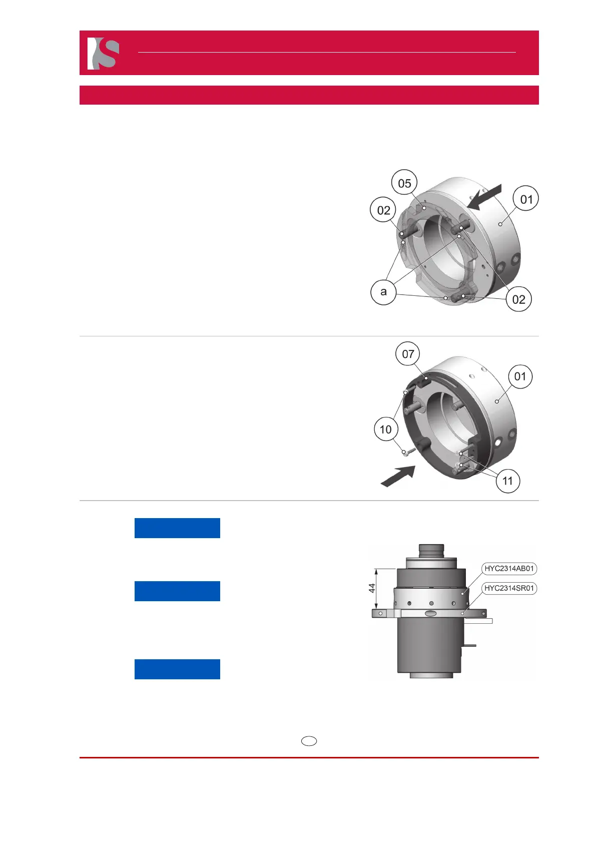
Mounting the Actuator Housing HYC2314S01 on the Single Axis Valve Gate 16SVH
1) Mount the actuator housing (1, Part of HYC2314S01) with the pistons
(2, Part of HYC2314S01) into the related holes of the suspension ring
(5, Part of HYC2314S01).
2) Turn the pistons (2, Part of HYC2314S01) to align the holes (a) at the
pistons ( 2, Part of HYC2314S01) regarding the holes at the suspension
ring (5, Part of HYC2314S01).
3) Take the actuator housing (1, Part of HYC2314S01) away from the
suspension ring (5, Part of HYC2314S01).
Doc003297.png
4) Attach the Protection ring (07, Part of HYC2314S01) with hexagon
socket cap screws (10 and 11, Part of HYC2314S01) at the actuator
housing (01, Part of HYC2314S01).
Doc003300.png
5) Check the t of the adjustment bushing HYC2314AB01).
NOTICE
The adjustment bushing HYC2314AB01 has to be positioned
20 mm to the upper edge of the guide sleeve and fixed with
the hexagon socket set screw (19).
NOTICE
The inside thread of the suspension ring (HYC2314SR01) is
a left-hand thread.
6) Screw the suspension ring (HYC2314SR01) at the adjustment bushing
(HYC2314AB01).
NOTICE
The suspension ring (HYC2314SR01) has to be positioned
44 mm to the upper edge of the guide sleeve (N9).
Doc007376.png
 Loading...