3 I56-6649-000
2/24/2020
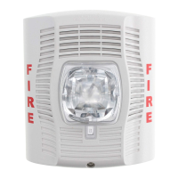
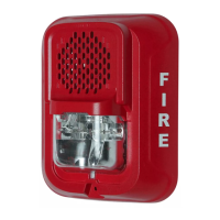
FIGURE 7. WALL MOUNT LOW-FREQUENCY SOUNDER STROBE WITH
JUNCTION BOX
A0583-00
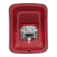
FIGURE 8. WALL MOUNT LOW-FREQUENCY SOUNDER STROBE WITH
SURFACE-MOUNT BACK BOX
A0584-00
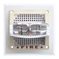
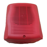
FIGURE 9. COMPACT WALL MOUNT LOW-FREQUENCY SOUNDER
SOUNDER WITH LED ALARM INDICATOR AND SILENCE SWITCH, IN
JUNCTION BOX
Silence Switch/LED Indicator
A0585-00
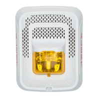
FIGURE 10. COMPACT WALL MOUNT LOW-FREQUENCY SOUNDER WITH
LED ALARM INDICATOR AND SILENCE SWITCH, IN SURFACE-MOUNT
BACK BOX
A0586-00
TONE AND CANDELA SELECTION
Tables 1 and 2 list current draw and sound output for available settings. Fig-
ures 14 – 15 list the minimum light output requirements per ULC.
Sounder tone and volume: Turn the rotary switch on the back of the product.
Candela: Adjust the slide switch on the rear of the product to the desired can-
dela setting. Candela setting will display in the small window on the front of
the unit. All products meet the light output profiles specified in the appropri-
ate ULC Standards.
TABLE 2. LOW FREQUENCY WALL AND CEILING SOUNDER ONLY
CURRENT DRAW (mA)
Pos
Sound
Patterns
Volume
Setting
Current Draw
(mA)
Sound Output
(dBA) Reverberant
Sound Output
(dBA) Anechoic
16–33 Volts
16-33 V 16-33 V
DC FWR DC FWR DC FWR
1
Temp 3
High
108 150
80 80 82 82
2
Low
78 76
76 76 78 78
3
Temp 4
High
111 151
80 80 82 82
4
Low
80 76
76 76 78 78
5
Contin-
uous
High
111 151
80 80 82 82
6
Low
80 76
76 76 78 78
7*
Coded
High
111 151
80 80 82 82
8*
Low
80 76
76 76 78 78
*NOTE: For coded tones, temporal coding must be provided by the NAC. If the
NAC voltage is held constant, the sounder output will remain constantly on.
Coded ratings provided are for continuous voltage.
TAMPER SCREW
For tamper resistance, the standard
captive screw may be replaced with
a Torx screw, ordered separately.
To remove the captive screw, back
out the screw and apply pressure
to the back of the screw until it dis-
engages from the housing. Replace
with Torx screw. (See Figure 11.)
FIGURE 11. TAMPER SCREW
T15 Torx
#6-32, 5/8"
SCREW-TMPR-50
A0478-00
FIGURE 12. SURFACE MOUNT BACK BOX UP ARROW
A0481-00
FIGURE 13. KNOCKOUT AND V500/V700 REMOVAL FOR SURFACE
MOUNT BACK BOX
½ inch
or ¾ inch
Wire Mold Removal
A0465-01
A0466-01
TABLE 1. WALL SOUNDER STROBE CURRENT DRAW (mA) AND SOUND OUTPUT (dBA)
Pos Tone
Volume
Setting
Current draw (mA)
Sound Output
(dBA)
Reverberant
Sound Output
(dBA)
Anechoic
16-33 VDC 16-33 FWR
16-33 V 16-33 V
15cd 30cd 75cd 95cd 110cd 135cd 185cd 15cd 30cd 75cd 95cd 110cd 135cd 185cd
DC FWR DC FWR
1
Temp 3
High 98 115 158 173 182 212 266 136 153 188 206 228 258 304 80 80 82 82
2 Low 98 102 141 162 173 202 255 150 150 176 194 216 242 280 76 76 78 78
3
Temp 4
High 98 108 137 151 178 202 252 200 198 169 188 212 242 290 80 80 82 82
4 Low 102 104 122 136 163 187 237 176 174 154 173 197 227 275 76 76 78 78
5
Contin-
uous
High 141 158 198 216 234 264 305 190 207 249 268 289 321 368 80 80 82 82
6 Low 120 128 179 196 215 244 285 165 182 226 244 266 297 342 76 76 78 78
 Loading...