Do you have a question about the System Sensor SPSRL and is the answer not in the manual?
Provides detailed information on speaker notification devices, wiring and special applications.
Observe NFPA 72 and NEMA guidelines for installation.
Notification appliance must be tested and maintained following NFPA 72 requirements.
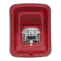
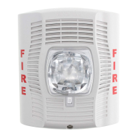
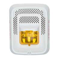
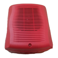
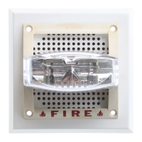
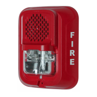
Indoor speaker strobes offer audible/visible notification, 7 field selectable candela settings.
Electrically backwards compatible with previous System Sensor speaker strobes.
Speaker listed to ANSI/UL 1480 (public mode), strobe to ANSI UL 1638 (public mode).
Install fire alarm speakers in compliance with NFPA 72, ANSI/UL 1480 and NEC 760.
Ensure loop current does not exceed panel supply capability.
Consider wire resistance for voltage drop; use website calculator for accuracy.
Limit strobes to 69 per NAC for 24-volt applications.
Adjust slide switch on rear for desired candela output.
Verify candela setting via a small window on the front of the unit.
Table detailing current draw (mA) for wall-mount strobes at various candela settings.
Table detailing current draw (mA) for ceiling-mount strobes at various candela settings.
Install wiring per National Electric Code and local codes; up to 12 AWG wire is supported.
Strip wire, place under clamping plate, and tighten screw.
Select voltage (25/70.7V) and wattage (1/4, 1/2, 1, 2W) using rear switches.
Enables continuity checks during wiring; disengages upon installation for supervision.
Products offer power settings including 1/4W, 1/2W, 1W, and 2W.
Table 3 shows sound levels (dBA @10 ft) for each transformer power setting.
Signal levels exceeding 130% rated voltage or incorrect tap selection can damage the speaker.
Attach mounting plate to junction box using provided screws.
Hook tabs, pivot to engage terminals, and secure with mounting screw.
Press locking button after loosening captive screw to remove from mounting plate.
Standard captive screw can be replaced with a Torx screw for tamper resistance.
Secure surface mount back box directly to wall/ceiling; grounding optional.
Wall mount box must be installed with the up arrow pointing up.
Use flat-head screwdriver to carefully remove knockouts, avoiding damage.
Use pliers to turn and remove V500/V700 raceway knockouts.
Speakers may not alert sound sleepers or those with hearing impairment.
Ambient noise like traffic or machinery may prevent alert persons from hearing.
Complies with FCC limits for commercial environments; may cause interference.
| Nominal Voltage | 24 VDC |
|---|---|
| Candela Rating | 15 cd |
| Color | White |
| Type | Speaker |
| Humidity Range | 10 to 93% non-condensing |
| Voltage Range | 16-33 VDC |
| Flash Rate | 1 Hz |
| Sound Output | 88 dBA @ 10 ft (3 m) |