I56-0022-000
INSTALLATION AND MAINTENANCE INSTRUCTIONS
ENGLISH
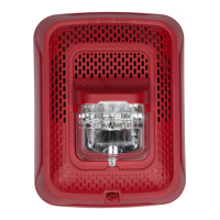
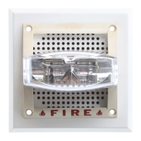
L-Series with LED
Indoor Selectable-Output
Horn Strobes and Strobes
3825 Ohio Avenue, St. Charles, Illinois 60174
800/736-7672, FAX: 630/377-6495
www.systemsensor.com
LED L-series Indoor Horn Strobes and Strobes — P/N I56-0022-000 8/25/2023 1
Manual is for use with the following models:
Horn Strobes
Standard Wall Mount Horn Strobes: P2RLED, P2RLED-B, P2WLED, P2WLED-B, P2RLED-P, P2WLED-P, P2RLED-SP, P2WLED-SP
Compact Wall Mount Horn Strobes: P2GRLED, P2GRLED-B, P2GWLED, P2GWLED-B
Standard Ceiling Mount Horn Strobes: PC2RLED, PC2RLED-B, PC2WLED, PC2WLED-B
2-Wire Strobes
Standard Wall Mount Strobes: SRLED, SRLED-B, SWLED, SWLED-B, SRLED-P, SWLED-P, SRLED-SP, SWLED-CLR-ALERT, SWLED-ALERT*
Compact Wall Mount Strobes: SGRLED, SGRLED-B, SGWLED, SGWLED-B
Ceiling Mount Strobes: SCRLED, SCRLED-B, SCWLED, SCWLED-B, SCWLED-CLR-ALERT, SCRLED-P, SCWLED-P
Language designators: “-B” are bilingual (English/French). “-P” are plain versions (no wording). “-SP” are marked “FUEGO”
*Amber lenses are for use in UL applications.
Table of Contents
Section 1: Introduction .................................................................................................................................................. 2
1.1 Product Specifications .......................................................................................................................................................2
1.2 Dimensions and Mounting Options ...................................................................................................................................2
1.3 Before Installing ................................................................................................................................................................2
1.4 General Description ..........................................................................................................................................................2
1.5 Fire Alarm System Considerations ....................................................................................................................................3
1.6 System Design ..................................................................................................................................................................3
Section 2: Configurations for Notification Appliances ............................................................................................... 4
2.1 Available Tones .................................................................................................................................................................4
2.2 Available Candela Settings ...............................................................................................................................................4
2.3 Current Draw and Audibility ratings ...................................................................................................................................5
Section 3: Installation .................................................................................................................................................... 7
3.1 Wiring and Mounting .........................................................................................................................................................7
3.2 Wiring Diagrams ................................................................................................................................................................7
3.3 Install Back Box .................................................................................................................................................................7
3.4 Install Mounting Plate and Appliance ................................................................................................................................7
3.5 Remove a Ceiling Model Appliance ..................................................................................................................................8
3.5.1 Mounting Drawings ........................................................................................................................................................8
3.6 Tamper Screw .................................................................................................................................................................10
3.7 Test Points ......................................................................................................................................................................10