D400-40-00 1 I56-609-03
SP100 Series Dual Transformer
Speakers and Speaker/Strobes for
Fire Protective Signaling Systems
INSTALLATION AND MAINTENANCE INSTRUCTIONS
A Division of Pittway
3825 Ohio Avenue, St. Charles, Illinois 60174
1-800-SENSOR2, FAX: 630-377-6495
NOTICE: This manual should be left with the owner/user
of this equipment.
General Description
The National Fire Protection Association (NFPA) has pub-
lished standards and recommended practices for the speak-
ers described in this manual. As a result, the installer must
be familiar with these requirements as well as all local
codes and special requirements of the authority having ju-
risdiction.
SP100 series speakers can be operated with distribution
amplifiers having an output voltage of either 25 volts or
70.7 volts.
The speakers operate at any one of six input power levels.
The output sound level is selected at the time of installa-
tion, but can be changed, if necessary.
The speaker is also equipped with a capacitive input to al-
low for DC supervision.
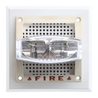
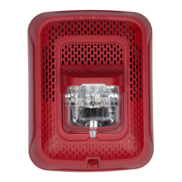
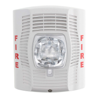
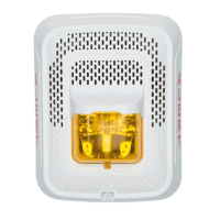
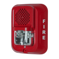
An optional, attached 1.5 or 15 candela (cd) strobe is also
available from System Sensor for use with the speaker. Al-
though they are shipped as a unit, the strobe and speaker
are electrically independent and require separate power
sources. Strobes can be powered by means of a full-wave
rectified unfiltered supply.
Figure 1. Electrical connections:
Specifications
Mechanical
Input Terminals: 12 to 18 AWG (3.31 to 0.82 mm
2
)
Speaker Size: 4 inches (101 mm)
Grille Size
Round: 7-3/8" (187 mm)
Square: 5" (127 mm)
Electrical
Voltage Input: 25 volts or 70.7 volts (nominal)
Frequency Range: 400 - 4000 Hz
Operating Temperature Range: 32° to 120°F (0° to 49°C)
Installation
All wiring must be installed in compliance with the Na-
tional Electrical Code and all applicable local codes as well
as any special requirements of the authority having juris-
diction, using the proper wire size. This also includes all
applicable NFPA Standards, ANSI/UL 1480, and NEC 760.
Electrical
1. Connect the speaker and strobe (if used) as shown in
Figure 1. Keep in mind that even though the speaker and
optional strobe are a single mechanical unit, they are
electrically independent and require separate power
sources.
NOTE: Do NOT loop electrical wiring under terminal
screws. Wires connecting the device to the control
panel must be broken at the device terminal con-
nection in order to maintain electrical supervision.
2. Notice that the speaker circuit board is equipped with
two sets of posts and associated electrical jumper wires.
One set of posts is numbered 1 through 6 while the other
is labeled A and B. Both electrical leads are fitted with a
barrel connector. These two sets of posts and leads en-
able the installer to select any one of six sound pressure
levels with either a 25 volt or 70.7 volt amplifier.
Technical Manuals Online! - http://www.tech-man.com