D900-02-00 1 I56-655-03
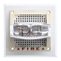
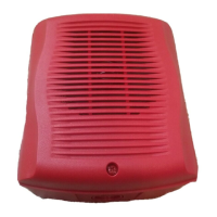
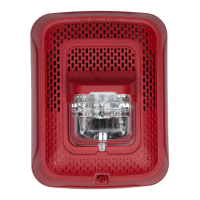
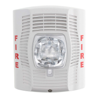
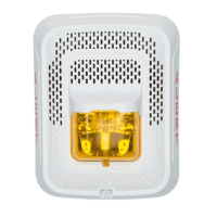
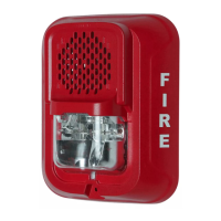
V4R24ADA Series Speaker/Strobes
for Fire Protective Signaling Systems
INSTALLATION AND MAINTENANCE INSTRUCTIONS
A Division of Pittway
3825 Ohio Avenue, St. Charles, Illinois 60174
1-800-SENSOR2, FAX: 630-377-6495
General
The National Fire Protection Association has published
standards and recommended practices for the installation
and use of the appliances described in these instructions. It
is recommended that the installer become familiar with
these standards and practices, local codes, and any special
requirements of the authority having jurisdiction.
The speakers can operate at any one of four input power
levels at either of two input voltages. The system voltage
and sound power levels are selected at the time of installa-
tion, but can be changed, if necessary.
Strobe
Specifications
Speaker
Frequency Range: 400 Hz to 4000Hz
Supervision: Capacitive input for supervisory DC voltage
Mounting: Standard 4" X 4" electrical box
Surface mount directly to box
Semiflush mount, using model MP-SF or MP-SFB
Model Supply
Voltage
Range
Operating Current from
Regulated Supply
Operating Current from Full-Wave
Rectified Unfiltered Supply
Average
Operating
Current
Average
Operating
Current
(mArms)
Peak
Current
(mA)
20Vrms/
30Vrms
Peak
Current
(mA)
20/30V
Inrush
Current
(mA in
access
of Peak)
Inrush
Current
(Amps in
excess
of Peak)
V4R24110ADA
V4R2475ADA
V4R2415ADA
V4R241575ADA
20-30V 210 470/500 0 245 400/500 0.08
20-30V 170 385/400 0 200 320/370 0.04
20-30V 75 160/180 0 90 275/290 0.02
20-30V 93 210/220 0 120 275/290 1.0
NOTE: Inrush current duration is less than 20 microseconds (.00002 seconds).
Input
Voltage
(Vrms)
Power
Tap
(Watts)
Minimum Output (dBA)
UL
Reverberant
Anechoic
@ 10 ft.
25 or 70.7 1/4 75 78
25 or 70.7 1/2 78 81
25 or 70.7 1 81 84
25 or 70.7 2 84 87
The speaker is also equipped with a capacitive input to al-
low for DC supervision.
An attached 24 VDC strobe at 110, 75, 15, or 15/75 candela
(cd) is also included with the speaker. Although they are
assembled into a unit, the strobe and speaker are electri-
cally independent and require separate power sources.
Strobes can be powered by means of a full-wave rectified
unfiltered supply.
Technical Manuals Online! - http://www.tech-man.com