LED L-series Indoor Horn Strobes and Strobes — P/N I56-0022-000 8/25/2023 7
Section 3: Installation
3.1 Wiring and Mounting
All wiring must be installed in compliance with the National Electric Code (UL applications), (Canadian Electric Code (ULC applications),
and local codes as well as the authority having jurisdiction. Wiring must not be of such length or wire size which would cause the notifica-
tion appliance to operate outside of its published specifications. Improper connections can prevent the system from alerting occupants in the
event of an emergency.
Wire sizes up to 12 AWG (2.5 mm²) may be used with the mounting plate. The mounting plate ships with the terminals set for 12 AWG field
wiring.
Make wire connections by stripping about
3
/
8
" of insulation from the end of the field wire. Then slide the bare end of the wire under the
appropriate clamping plate and tighten the clamping plate screw.
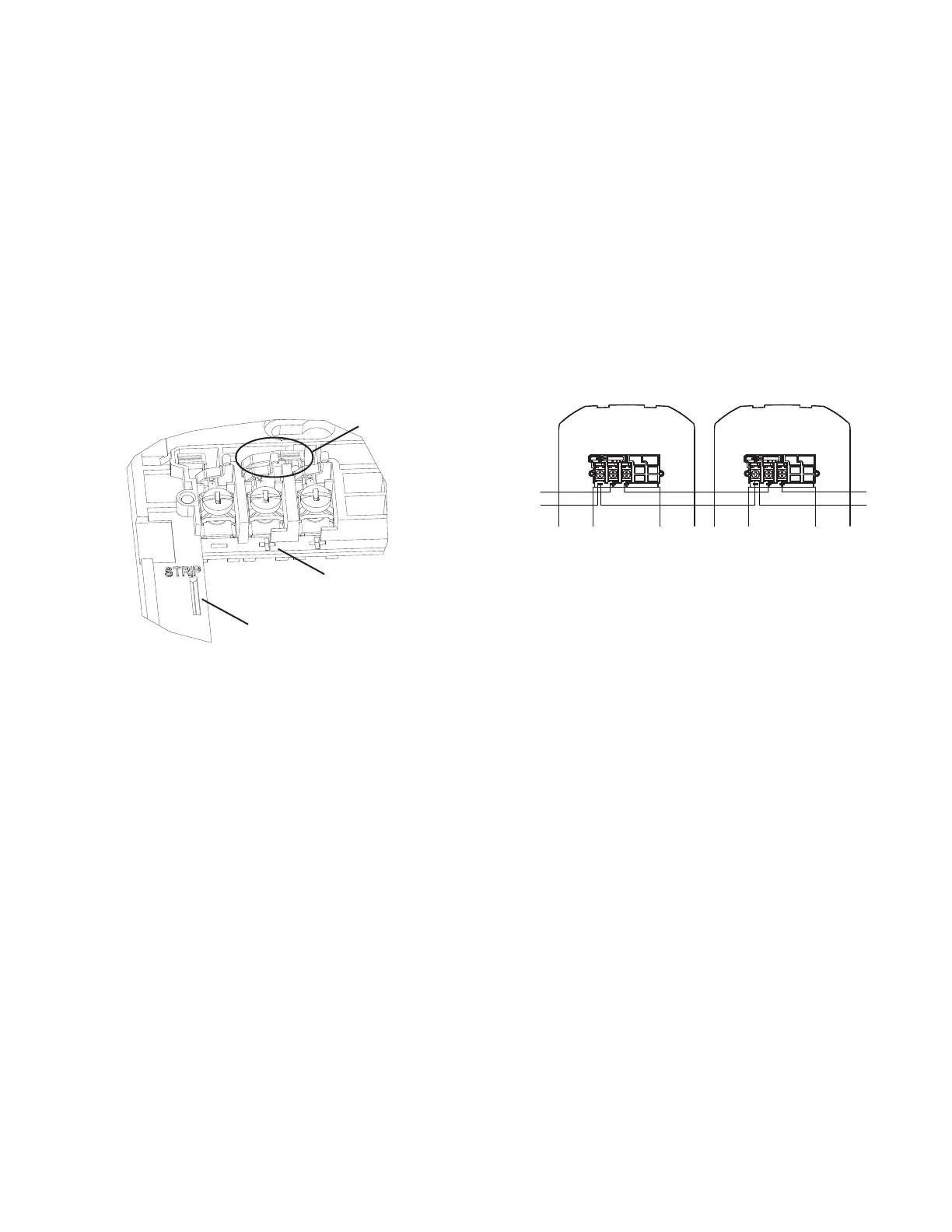
We provide a wire strip guide. See Figure 6 for wiring terminals and strip guide reference.
3.2 Wiring Diagrams
The 2-wire horn strobe and strobe only require two wires for power and supervision. (See Figure 7.)
Shorting Spring Feature. These appliances enable system continuity checks of field wiring on the mounting plate before appliances are
installed. The mounting plate has a shorting spring between terminals 2 and 3 that will automatically disengage when the product is installed,
to enable supervision of the final system. (See Figure 6.)
Figure 6 Wiring Terminals, Shorting Spring, and
Strip Guide
Figure 7 System Wiring
3.3 Install Back Box
1. Attach back box to wall or ceiling.
– Junction boxes are mounted per industry standard. (See Figures 8, 9 and 12.)
– The surface mount back box may be secured directly to the wall or ceiling. Use of grounding bracket with ground screw is optional.
(See Figures 10, 11 and 13.)
– Note for positioning: Wall mount back boxes: Mount with the up arrow pointing up. (See Figure 16.)
– Note for positioning: Ceiling mount back boxes: Ceiling surface mount back box SBBCR/WL is a common back box for ceiling
horn strobes, strobes, speakers, and speaker strobes. Use the top (SPK) mounting holes for ceiling speaker and speaker strobe
products. Use the bottom (STR) mounting holes for ceiling horn strobe and strobe installation needs.. (See Figure 15.)
2. Select appropriate knockouts and open as needed.
– Threaded knockout holes are provided for the sides of the box for ¾ inch and ½ inch conduit adapter. Knockout holes in the back of
the box can be used for ¾ inch and ½ inch rear entry.
– If using the ¾ inch knockout: To remove the ¾ inch knockout, place the blade of a flat-head screwdriver along the outer edge and
work your way around the knockout as you strike the screwdriver. (See Figure 17a.)
NOTE: Use caution not to strike the knockout near the top edge of the surface mount back box.
– V500 and V700 raceway knockouts are also provided. Use V500 for low profile applications and V700 for high profile applications.
To remove the knockout, turn pliers up. (See Figure 17b.)
3.4 Install Mounting Plate and Appliance
1. Attach mounting plate using the provided Philips head screws. Junction box uses 2 screws. Surface mount backbox uses 4 screws. (See
Figures 8 – 13.)
2. Connect field wiring according to terminal designations. (See Figures 6 and 7.)
3. If the product is not to be installed at this point, use the protective dust cover to prevent contamination of the wiring terminals on the
mounting plate.
4. To attach product to mounting plate:
– Remove the protective dust cover.
– Hook the tabs on the top of the product housing into the grooves on mounting plate.
Shorting Spring
Strip Guide
WIRING TERMINALS
1. Negative (-). Line in and out
2. Positive (+). Line in and out
3. Positive (+). Line in and out
+
–
+
–
INPUT
FROM
FACP
OR
PRIOR
DEVICE
OUTPUT
TO
NEXT
DEVICE
OR EOL